Do you have a question about the Megger 210170 and is the answer not in the manual?
Essential safety warnings and precautions for instrument usage, including circuit isolation and test lead conditions.
Explanation of safety symbols found on the instrument, indicating electrical hazards and cautionary notes.
Procedure for using the instrument as a voltmeter (0-600V a.c.) without pressing the test button.
Steps to perform low resistance (Ω) measurements using the rotary selector and test push.
Instructions for performing insulation tests (MΩ) including lead connection, test execution, and discharge monitoring.
Explanation of how to use the guard terminal to mitigate surface leakage effects in insulation testing.
Detailed specifications for Insulation, Terminal Characteristics, Low Resistance, and Default Voltage measurements.
Details on operating/storage temperature, humidity, automatic discharge, and power supply for the instrument.
Information on the instrument's fuses, including type, rating, and the procedure for replacement.
Instrument weight, dimensions, and recommended cleaning procedures.
List of accessories supplied with the instrument and available optional items.
Details on the 1-year warranty, note on unauthorized repairs, and contact information for service and spare parts.
Guidance on authorized repair companies and the process for returning the instrument for repair.
| Brand | Megger |
|---|---|
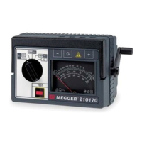
| Model | 210170 |
| Category | Test Equipment |
| Language | English |