Do you have a question about the Megger BITE 2 and is the answer not in the manual?
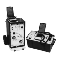
Overview of the BITE 2 and BITE 2P test instruments.
Explanation of the BITE 2/2P testing methodology and principles.
Lists battery types and system types tested by BITE 2/2P.
Details impedance, voltage, and current measurement specifications.
Instructions for checking equipment upon delivery and initial setup.
Directs user to read safety information in Chapter 2.
Explains manual structure, typographic conventions, and notes.
General safety considerations for using electrical test equipment.
Lists safety standards and operational precautions for battery testing.
Details safe power source connection procedures and requirements.
Guidance on fuse replacement and general warnings.
Introduces controls, connectors, and menus for BITE 2/2P.
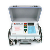
Details front panel controls, indicators, and connectors for BITE 2.
Details front panel controls, indicators, and connectors for BITE 2P.
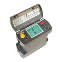
Describes receiver display, probes, trigger, connectors, and power.
Explains receiver keys for navigation and the reset switch.
General overview of the BITE 2/2P testing procedure.
Pre-test activities including visual inspection and recording data.
Procedure for powering on the receiver and initial screens.
Optional scanning of test info using a bar-code wand.
Setting reference values for test interpretation.
Procedure for splitting a strap measurement if needed.
Connecting the BITE 2/2P transmitter to the battery.
Detailed steps for measuring cell and strap impedance.
Actions after test completion: export, print, delete, power down.
Alternative test procedures and optional equipment.
Procedure for reversing leads for high/low current issues.
Techniques for testing batteries over 275V or with parallel strings.
Explains how to manage test results.
Steps to transfer test data to a computer.
Instructions for printing results using the BITE 2P printer.
How to remove unwanted test data from the receiver.
Factors to consider when interpreting test outcomes.
Instantaneous, short-term, and long-term analysis of results.
Adjusting impedance readings based on temperature.
How to customize receiver settings for optimal use.
Adjusting backlight and screen contrast.
Setting language, date, time, and line frequency.
Guide to maintaining the BITE 2/2P and interpreting errors.
Procedures for cleaning instrument components and leads.
Charging and replacing the receiver's Ni-Cd battery pack.
Identifying and replacing primary and secondary fuses.
Lists optional accessories for the BITE 2 and BITE 2P.
Details the BITE 2/2P's testing capabilities and limits.
Provides electrical parameters for transmitters and receiver.
Lists fuse types, dimensions, weight, and operating environment.
Lists part numbers for standard accessories.
Lists part numbers for optional accessories.
Instructions on how to order replacement parts.
Introduces Megger's AVOLINK software for data management.
Lists hardware and software requirements for AVOLINK installation.
Step-by-step guide to installing the AVOLINK software.
Instructions for connecting and using AVOLINK with BITE devices.
Steps to transfer test data from BITE to PC.
How to open, view, and print transferred test files.
Settings for communication parameters and testing.
| Accuracy | ±2% of reading ±2 digits |
|---|---|
| Display | LCD |
| Operating Temperature | 0°C to +50°C (32°F to +122°F) |
| Storage Temperature | -20°C to +60°C (-4°F to +140°F) |
| Resistance Range | 0.01 Ω to 20 kΩ |
| Frequency Range | 50 Hz to 60 Hz |
| Battery Life | Typically > 8 hours continuous testing |