M
AVTM246004 BITE 2/2P Rev 4 July 2011
28
Step Two: Powering-on the Receiver
After you successfully perform the pretest activities described
Step One, you are ready to power on the receiver.
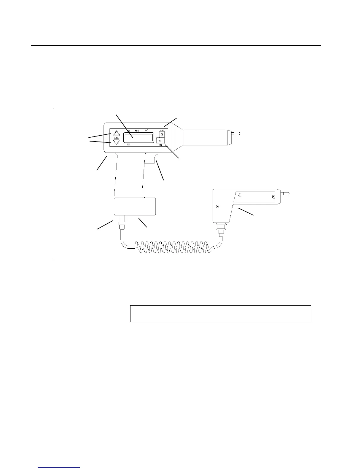
POWER ON
Switch
ENTER Key
7-Pin
Connector
4-Pin
Connector
Potential
Probe
3-Pin
Connector
LCD
TRIGGER
UP and
DOWN
ARROW
Keys
Figure 4-1: Receiver controls, connectors and indicators
1. Make sure the receiver charger is disconnected from the
receiver.
NOTE: Do not use the receiver to perform tests while the
charger is connected to the receiver.
2. Connect the potential probe cable assembly to the 7-pin
connector on the receiver.
3. Press the POWER ON switch on the receiver.
The receiver powers on and displays several initialization
screens.
www.GlobalTestSupply.com
Find Quality Products Online at: sales@GlobalTestSupply.com