STANDARD TEST PROCEDURE
AVTM246004 BITE 2/2P Rev 4 July 2011
39
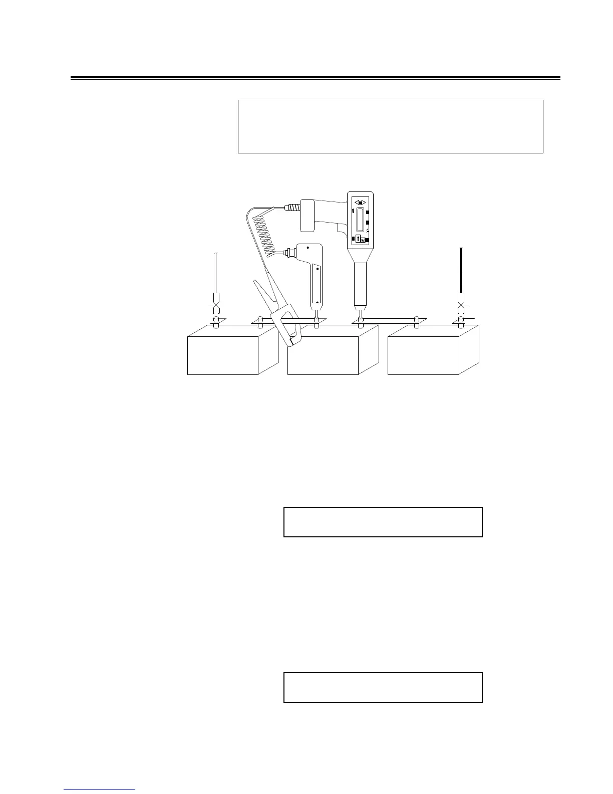
NOTE: The reason the receiver should be positioned on the
positive terminal is to obtain a positive float voltage of the cell.
Then a cell that has gone into “cell reversal” becomes very
evident when it displays a negative float voltage.
connected to negative
from Transmitter
Current Source Lead
Red
Black
terminal plate
Current Source Lead
from Transmitter
connected to positive
terminal plate
Figure 4-6: Receiver and potential probe positioned
on top of battery cell terminals
2. View the cell terminal voltage and ac impedance values
that are displayed on the receiver screen.
A sample screen is shown below.
CELL VOLTS mΩ
001 13.43 23.33
T01
The measurements are stored
in the receiver.
3. When the voltage and impedance values displayed on the
screen stabilize, pull the trigger on the receiver to store
the reading.
If you have entered baseline, warn and fail values, the
screen will display either PASS, WARN or FAIL and a
percentage of baseline.
001
T01 PASS XX%
www.GlobalTestSupply.com
Find Quality Products Online at: sales@GlobalTestSupply.com