EasyManuals Logo

Megger HPG AC Series User Manual

Megger HPG AC Series
34 pages
To Next Page IconTo Next Page
To Previous Page IconTo Previous Page
Page #15 background imageLoading...
Page #15 background image
15
The HV transformer should be connected with the test object
using a direct connection (wire or bus bar). It is also possible to
connect them with a short cable connection (6 to 10 m). Longer
cable connections do not make sense, since the remaining test
performance would be too low.
3.1.1 HPG 35-AC
This test system consists of the following components:
1. Control unit HSW 3-2
2. HV transformer HTR 35-1
3. Cable set VL 70
4. Discharge rod EST 50
3.1.2 HPG 58-AC
This test system consists of the following components:
1. Control unit HSW 3-2
2. HV transformer HTR 58-1
3. Cable set VL 70
4. Discharge rod EST 100
3.1.3 HPG 78-AC
This test system consists of the following components:
1. Control unit HSW 3-2
2. HV transformer HTR 78-1
3. Cable set VL 70
4. Discharge rod EST 100

Table of Contents

Questions and Answers:

Question and Answer IconNeed help?

Do you have a question about the Megger HPG AC Series and is the answer not in the manual?
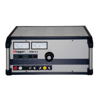
Megger HPG AC Series Specifications

General IconGeneral
DisplayDigital meters for voltage and current
Protection FeaturesOverload protection, overvoltage protection
CoolingAir-cooled
WeightVaries by model (typically 50 kg to 200 kg)
DimensionsVaries by model
TypeHigh Voltage AC Test Set
ApplicationHigh voltage testing of electrical equipment and insulation

Related product manuals