10
your type of socket outlets, do not use an adaptor. You may change the
plug once only by cutting the cord as close to the plug as possible and
fitting a suitable plug.
The colour code of the cord is:
Earth (Ground) Yellow/Green
Neutral Blue
Phase (Line) Brown
Note: A plug severed from the power cord must be destroyed, as a plug
with bare conductors is hazardous in a live socket outlet.
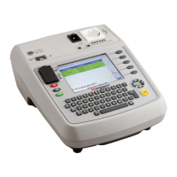
Test lead connection
The supplied test leads should be connected to the appropriate sockets on
the rear of the instrument marked L0 and L1, or to the 3 way test socket.
Standard test probes and crocodile clips are supplied for connection to the
circuit under test.
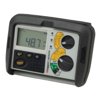
The test lead supplied with the LRCD200, LRCD210 and LRCD220 provides
connection for 3 wire testing, using the 3 wire (red, black and green) lead
set (6220-782) or mains plug lead (6220-740).
Application
This instrument may be connected live to earth or between live
conductors of systems that have a rated voltage of 300V a.c. rms to earth
and an installation (overvoltage) Category III or lower.
This means that the instrument may be connected to any fixed wiring of a
building installation, but not to primary supply circuits such as overhead
cables. To maintain user safety and ensure accurate measurements, only
use the test leads supplied or by Megger Limited.
swapped) or ‘L+N’ (instrument will not perform tests with L & N
swapped).
6. Press the [LOCK] button or the PFC button to change the setting.
7. Press the [TEST] button to exit from the set-up menu.
RCD Touch voltage selection
TToo sseett tthhee ttoouucchh vvoollttaaggee iinnhhiibbiitt lliimmiitt::
1. With the instrument switched OFF, hold down the [TEST] button and
turn the range knob to any ON position.
2. Keep the button held down until the instrument displays the ‘SET’
warning.
3. Now release the [TEST] button.
4. Press the [TEST] button twice to view the current settings for the touch
voltage.
The display shows the fault voltage limit, ‘25 V’ or ‘50 V’.
If the fault-voltage display is active, a bar-graph display will also appear.
5. Press the [0º/180º] button to change the limit setting from 25V to 50V
and back.
6. Press the [TYPE] button to turn bar-graph display ON or OFF.
7. Press the [TEST] button to exit from the set-up menu.
Test leads
All test leads form part of the measuring circuit of the instrument and
must not be modified or changed in any way, or be used with any other
electrical instrument or appliance.
The mains plug test lead supplied with the Megger Tester is a test lead that
forms part of the measuring circuit of the instrument. The overall length
of this lead must not be altered. If the power cord plug is not suitable for
 Loading...