LED indicators
Three RED led indicators show circuit connection status when correctly
connected to a live circuit. These are for indication purposes only and
should not be relied upon as a indication of the presence of a hazardous
voltage.
When connected to the circuit to be tested the three status LED’s will
show the following supply connection information:
LED Normal Reversed Notes
Indicator Supply (L-N) supply
=ON = OFF
L - PE Voltage between L- PE
greater than 25 V
L - N Voltage between L-N
greater than 25 V
N - PE Voltage between N-PE
greater than 25 V
WWaarrnniinngg::
Voltage indicator LED’s cannot reveal a N-PE supply reversal
Polarity Indication
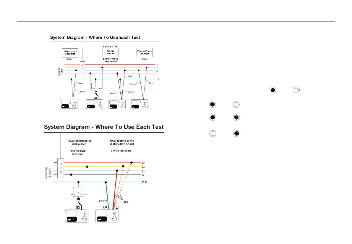
If connected to a single phase power supply by a plug or by the 3-wire
lead set, three LED’s marked L-PE, N-PE and L-N will indicate supply
polarity
Note: The presence of a voltage between phase and earth does not prove
earth continuity, as the earth could have a high resistance and a voltage
would still be measured. To test earth continuity refers to the sections on
loop testing.
11
LRCD220
LRCD220
LOOP TESTING
RCD TESTING
 Loading...