9 | Page
OFF
ON
STANDING PILOT
SWITCH
“FIRST TIME” PILOT LIGHTING INSTRUCTIONS
IMPORTANT: Be sure all items on "INSTALLATION CHECK OFF LIST" in the Installation Manual have been completed!
CAUTION: If the pilot goes out, be sure to wait a minimum of five minutes before attempting to relight the pilot.
1. Make certain that any manual gas supply shut-off valves located upstream of fireplace are open and the wall receiver and the re-
mote control transmitter are in the "OFF" position. Make certain that the wall receiver harness is connected to the wall receiver
properly.
2. Make certain that 110VAC power is connected to Electrical Junction Box on left side of Fireplace and that the Electrical Power is
“ON”. See Figure 28.
3. Insert Batteries in the Wall Receiver and the Remote Transmitter. Note the polarity of batteries and insert as indicated on the bat-
tery compartment covers.
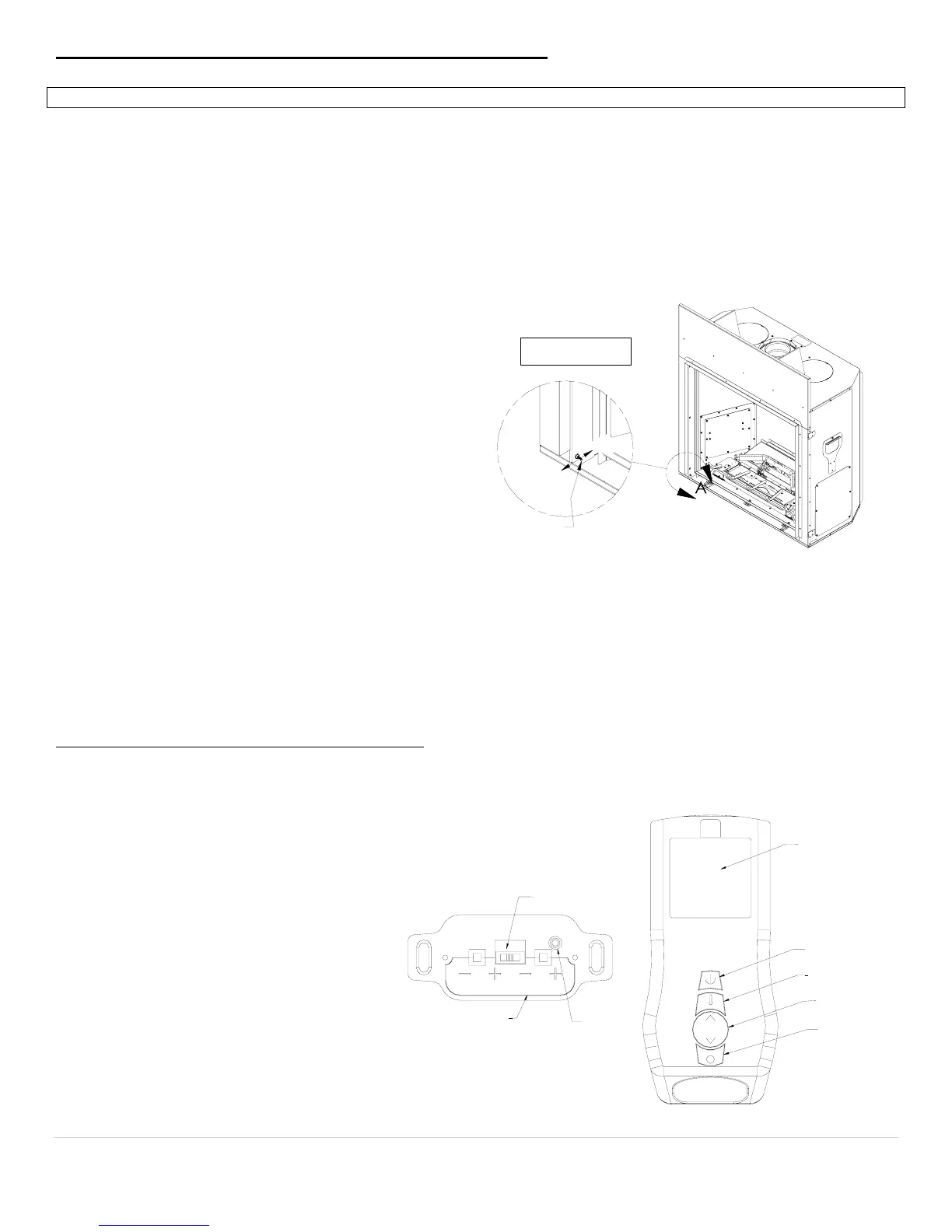
4. For the “First Time Lighting”, Remove the Glass Door. This is required to purge the gas line of air and to inspect the pilot light-
ing spark.
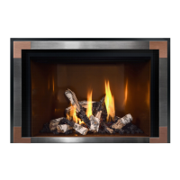
5. Slide the wall receiver switch to “REMOTE”. Locate the
“Standing Pilot ON/OFF Switch”. See Figure 1. Toggle
“Standing Pilot ON/OFF Switch” to “ON”. You will
hear a series of clicks and after a few seconds, you will
hear sparking at the pilot spark electrode.
6. Allow adequate time for the air in the gas-line to purge.
The control system will stop sparking after 30 seconds if
the pilot light does not light. After a 30 second delay the
control system will start sparking again for 30 seconds
more. If the pilot light does not light after the third 30
second spark event, the system will enter “Lock-out”
mode. To unlock from “Lock-out” mode, slide Wall
Receiver Switch to “OFF”, wait 30 seconds and slide
back to “Remote”. Repeat this sequence until the pilot
flame lights and the pilot is burning steadily.
7. Once the pilot flame is lit and well-established, close glass door. WARNING: NEVER IGNITE MAIN BURNERS WITH
GLASS DOOR REMOVED OR OPEN. Doing so will lead to damage to pilot flame sensor and spark electrode wire leads.
8. Slide switch on Wall Receiver to “ON”. All burners should ignite and run at “high-fire”. Slide Wall Receiver switch to
REMOTE after 15 seconds. Burner Flames will extinguish.
9. Perform gas inlet and outlet pressure tests and leak tests on field installed gas fittings and factory installed fittings in the gas valve
compartment, at this time. Note: Burners must be ON to check outlet pressures and to leak test gas train fittings upstream of main
gas valve.
INITIALIZING THE REMOTE CONTROL SYSTEM
(Synchronizing Receiver and Transmitter)
1. Place 3-position slider switch in Wall Re-
ceiver in the “Remote” position.
2. Locate “PRG” key on Wall Receiver Face.
Use the tip of a pen/pencil or a wire clip to
push the PRG button. The receiver will
beep 3 times indicating that it is ready to
synchronize with a Remote Transmitter.
3. Push the “ON” key on the Remote Trans-
mitter. The receiver will beep 4 times to in-
dicate that the Transmitter’s command is
accepted and sets to the particular code of
that Transmitter. The system is now initia-
lized.
NOTE: Use this Synchronizing procedure every
time the batteries are replaced in the Receiver
or the Transmitter.
FIGURE 1
BATTERY
COMPARTMENT
LID
3-POSITION
SLIDER SWITCH
PRG KEY
P
RG
WALL RECEIVER
REMOTE TRANSMITTER
BLUE LCD
DISPLAY
MODE
SELECTION KEY
UP/DOWN
SELECTION KEY
THERMOSTAT
SELECTION KEY
ON/OFF KEY