Installing a Remote Keypad
Ensure that the mains and battery power has been
disconnected and proceed as follows:
1. Connect each core of the 6-core cable to the
interface terminals "LEDCBA"(make a note of the
colours used for each connection).
2. Pass the yellow flying-lead behind the PCB and
connect it to the [L/S-] terminal.
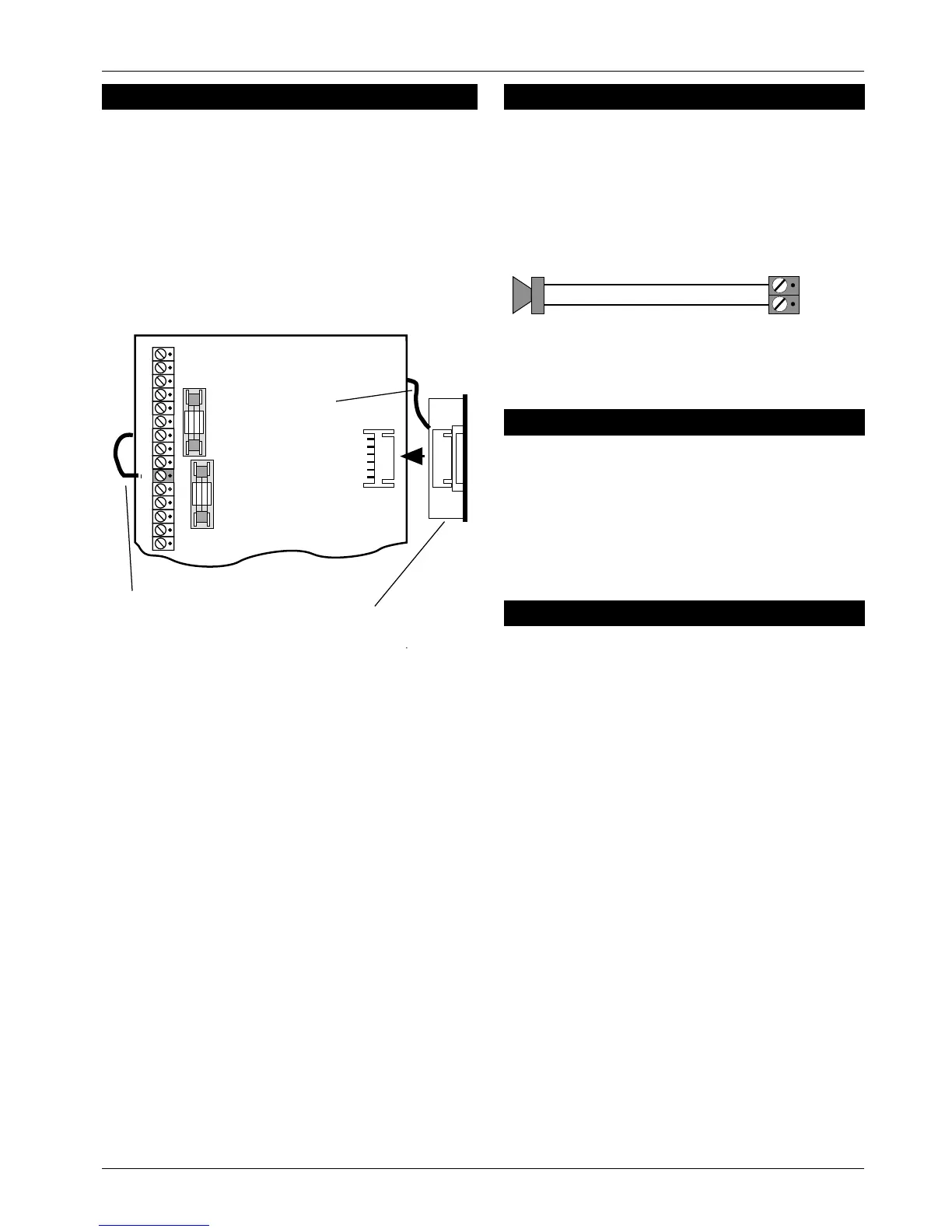
3. Plug the Interface board intotheinterface socket as
shown below:
4.
Separate the remote keypad cover and base by
using a screwdriver to push two of the clips (top or
bottom) inwards from the cover retaining slots. Then
lift the cover assembly, noting that the circuit board
is connected to the under side of the cover.
5. Holdtheremotekeypad base in position (keyholeto
the top) and mark the three securing holes,drill and
plug the wall as required. Pass the 6-corecable into
the base via the cable entry points as appropriate
and secure the base to the wall.
6. Connect each core of the 6-core cable to the
remote keypad terminals "LABCDE",ensuring that
the connections through to the control panel are A
to A, B to B, etc. If more remote keypads are to be
fitted, they may be connected in a star or daisy
chain configuration (providing the cable length to
the last or furthest remote keypad does not exceed
50 metres).
7. Carefully reattach the front cover assembly to the
remote keypad base ensuring that all cables are
clear of the tamper switch spring and the cover is
securely clipped to the base.
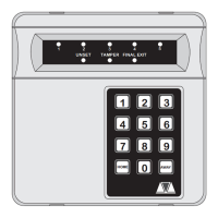
Extension Loudspeakers
A 16 Ohm extension loudspeaker can be connected
between the [L/S-] and [AUX 12V+] terminals. R37
(locatedinthetoplefthandcornerofthePCB)canbe
cut to reduce the volume of the internal sounders
(alarm is always full volume).
ALM- Terminal
This terminal is switched negative (100mA) on alarm
and is removed when the system is reset. If the Link
marked "HOME ALARM INHIBIT" on the main PCB is
closed, the [ALM-] output is disabled when the system
is part-set (Home). Normally this output is used to
trigger a speech dialler or similar.
RST- Terminal
This terminal may be programmed as:
Detector Reset (DTR RST)
WhenprogrammedasDetectorResettheoutputmay
be used for detectors which latch their alarm
condition, and must be de-powered to reset (e.g.
smoke detectors, vibration detectors etc.). Power for
such detectors must be connected between [AUX
12V] and [RST-].
Switched 12V (SW12V)
When programmed as Switched 12V the output may
be connected to the latch input terminal on latching
detectors (e.g., PIRs etc.). This featureis normallyused
when more than one detector is connected to a
single zone. It allows the user to identify the alarm
source by latching the indicator LED on the detector
that caused the alarmactivation. The latched LEDwill
clear when the system is reset.
496522 Issue A 5of10 TS400 & TS410
TS400 & TS410
InterfacePCB
Flying-lead
connectedtoL/S-
Flying-lead
L/S
Figure 3 Remote Interface Connections
16 Ohm Loudspeaker
L/S -
AUX +12V
Figure 4 Speaker Connections