Aux 12V Power
The auxiliary 12V terminals provide a permanent 12V
supply for detectors which require a low voltage supply
e.g., PIRs, vibration detectors, smoke detectors etc. The
output is protected by a 1 Amp fuse (Aux 12V).
The maximum available current from the control panel
power supply is 750mA. The following is a typical
example showing how to calculate the available
auxiliary current.
Control Panel = 85mA
External Sounder = 250mA
External Strobe = 115mA
Total = 450mA
Auxiliary Available = 300mA (750 - 450)
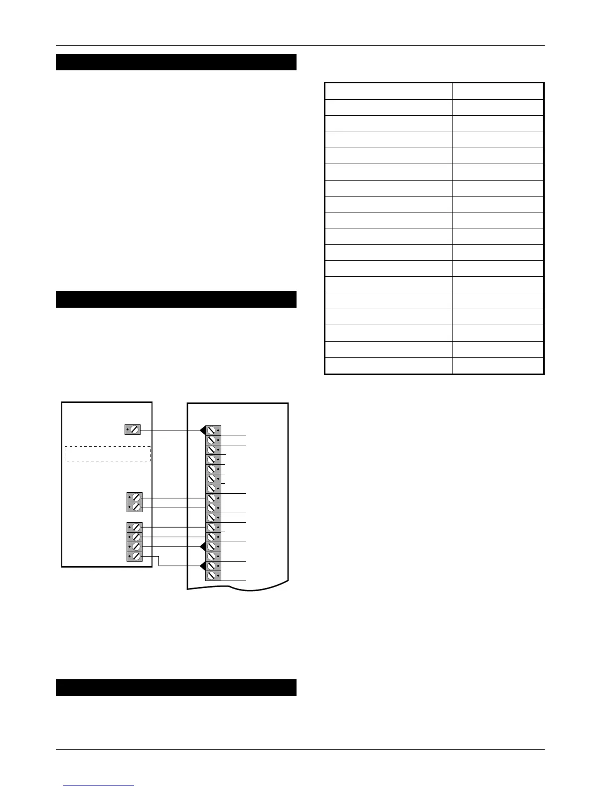
SD1+ (Optional)
The SD1+ is a customer programmable speech dialler
which dials pre-programmed numbers to inform
neighboursetc.ofthealarm.Itiscapableoftransmitting
up to 3 messages linked to inputs A, B and C.
Initial Power-Up
1. Place a small screwdriver blade between the pins
on the control panel PCB,markedFACTORY RESTART
(located just below the LEDs). This will ensure the
factory defaults are loaded as shown below:
Engineer Code 1234
User Code 1 5678
Zone 1 Alarm
Zone 2 Access
Zone 3 Alarm
Zone 4 Alarm
Zone 5 Alarm
Exit Time 30 Seconds
Entry Time 30 Seconds
Bell Duration 20 Minutes
Bell Output SAB (-ve applied)
Remote Reset Number 004
Setting Mode Timed Set
Reset Authority User Reset
Number Of Rearms 3
Operation Of Keyswitch Away Set (Full)
RST- Output Detector Reset
HOME Set Configuration Zone 1 Omitted
Factory Default Settings
2. Switch on the 240V mains supply, when the green
UNSET LED is lit remove the screwdriver blade. The
internal alarm will sound and the TAMPER LED will
light.
3. Enter the engineer’s passcode (default1234),
the alarm will silence. Enter the engineer’s
passcode again and the TAMPER LED will flash
(engineer programming menu selected).
4. Connect the standby battery. If the TAMPER LED
lights permanently and the internal alarm sounds
when the battery is connected, then it may be
incorrectly connected or it may be totally
discharged. Disconnect the battery immediately
and reconnect or replace as appropriate.
5. Push the battery into place at the bottom of the
housing and re-fit the front cover.
☞
On theTS410 you MUSTconnect the earth
bonding cable from the front cover to the
spade connection point.
6.
Fit the battery link in the external sounder and
replace cover.
7. The system is now ready for programming.
TS400 & TS410 6of10 496522 Issue A
TS400 & TS410
ALM -
RST -
TRG -
STB-
+
-
TMP -
AUX
TAMPER
L/S -
+
-
ZONE 5 (P A)
H/O
AUX 12V
ZONE 4 (Fire)
TRIG A
TRIG B
0V
+12V
TAMPER
BOX
TRIG C
Set TRIG POLARITY to -ve
Note: Only connect TRIG A (FIRE)
and TRIG B (PA) if zones 4 and 5
are programmed as Fire and PA.
TS400/TS410
SD
1+
Figure 5. SD1+ Connections Details