INSTALLATION MANUAL
Page 22 of 77 90-864198020
Models with V-Drive Transmissions
1. Lift engine into position in boat using an overhead hoist.
2. Install quick drain oil hose plug in oil drain hose.
3. Position engine so that enough propeller shaft protrudes through transmission and out-
put flange for propeller shaft coupler to be attached. Then install coupler and position
engine (no gap can be seen between coupling faces when butted together). Adjust en-
gine height if necessary to obtain proper alignment. DO NOT use mount adjustments
to adjust engine position at this time.
IMPORTANT: Engine bed must position engine so that a minimum of 1/4 in. (6 mm)
up and down adjustment still exists on all 4 mounts after performing final alignment.
This is necessary to allow for final engine alignment.
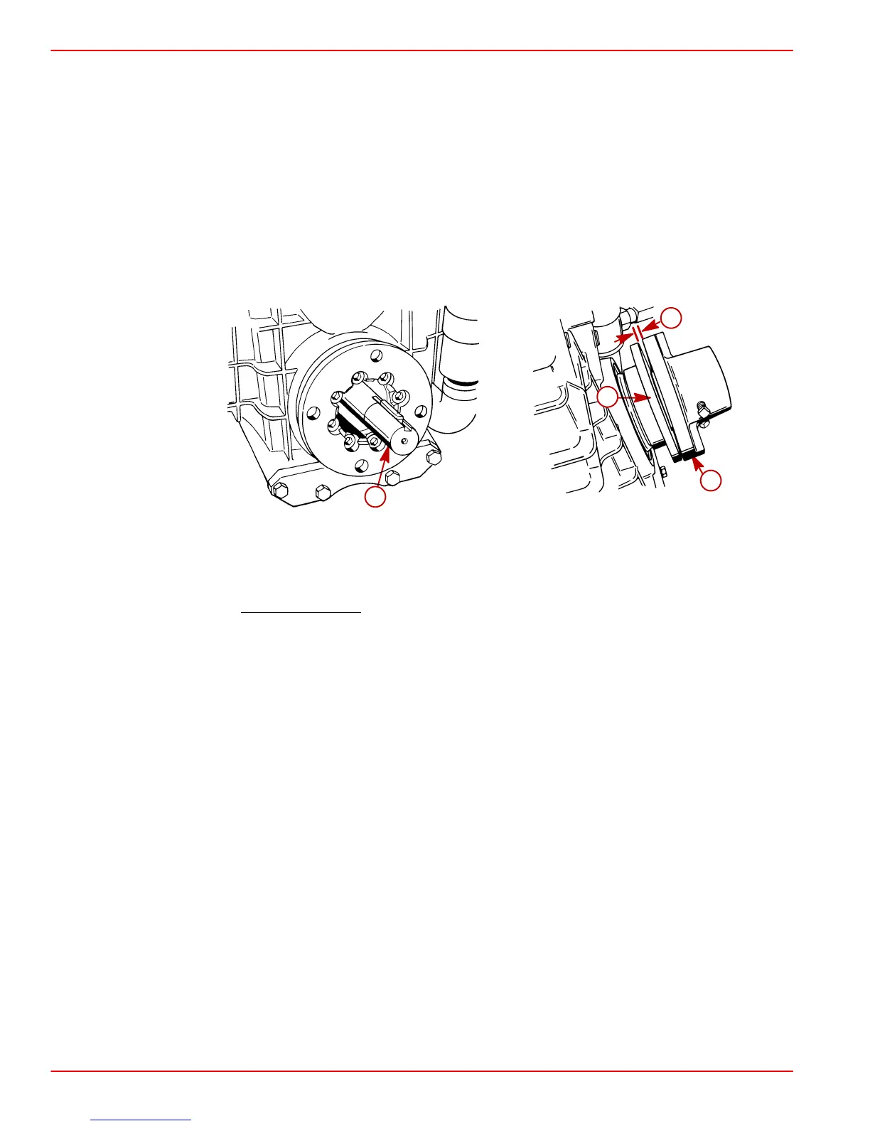
50608 50608
a
b
c
d
ZF / Hurth 630V (Others Similar)
a-Propeller Shaft
b-Propeller Shaft Coupler
c-Transmission Output Flange
d-No Gap Allowed
4. Ensure quick drain oil fitting is more than 1/2 in. (13 mm) above the boat bottom.
IMPORTANT: If quick drain oil fitting is within 1/2 in. (13 mm) of boat bottom, remove
fitting and install drain plug from parts bag directly into oil pan.
5. Ensure that all 4 mounts are still positioned properly. Fasten mounts to engine bed with
3/8 in. (10 mm) diameter lag bolts (of sufficient length) and flat washers. Tighten lag bolts
securely.
6. Disconnect overhead hoist and remove sling.
 Loading...