CYLINDER HEAD
Page 4A-16 90-857138R1 MAY 2000
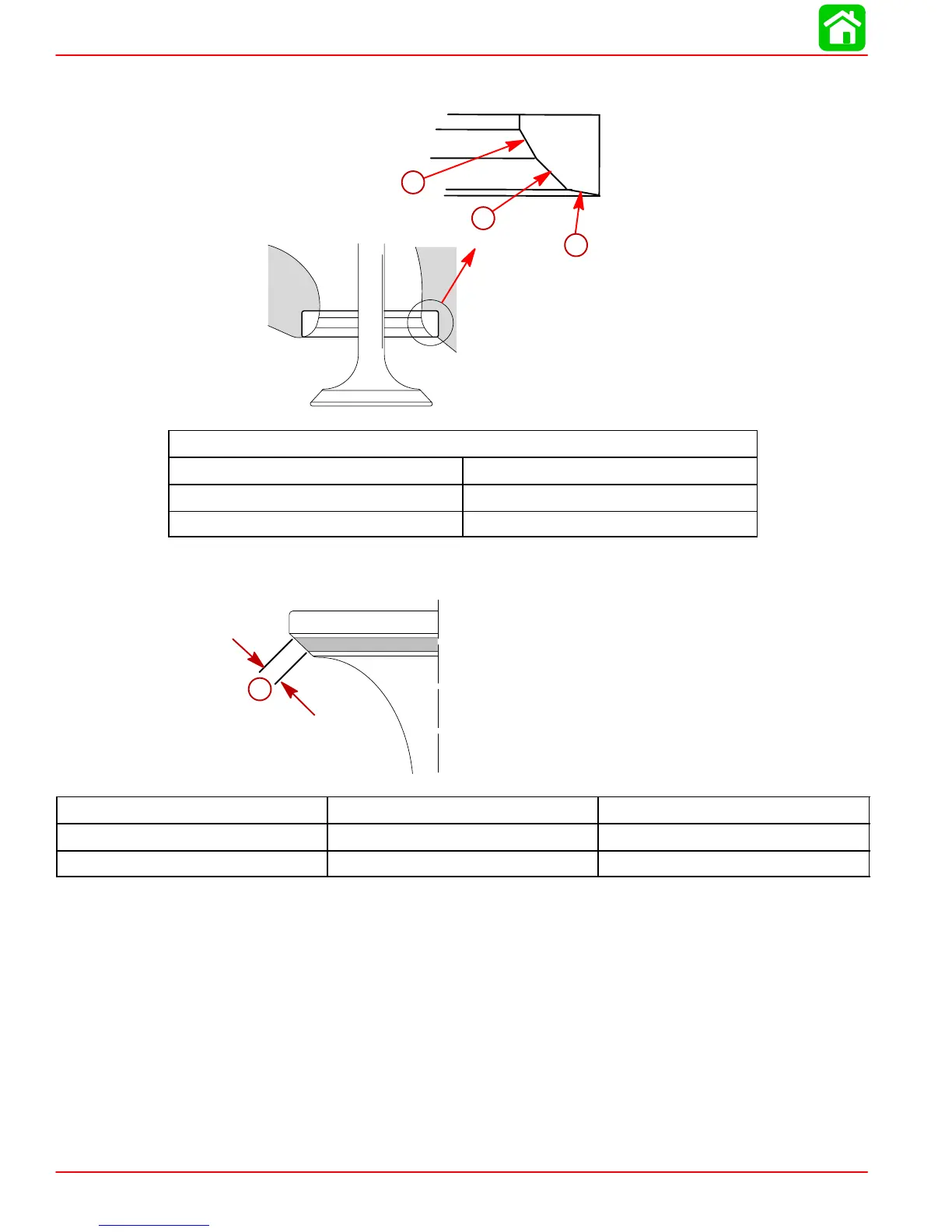
NOTE: If resurfacing the valve seats is required, resurface the valve seats to the specified
angle shown in chart.
55798
a
b
c
Valve Seat Angle Specifications
a 15°
b 45°
c 60°
CORRECT VALVE SEAT POSITION
55800
a
Standard Value “a” Limit that needs Repair
Intake Valve 0.031 in. (0.8 mm) 0.0708 in. (1.8 mm) or greater
Exhaust Valve 0.031 in. (0.8 mm) 0.0708 in. (1.8 mm) or greater
NOTE: After resurfacing the seats, inspect for even valve seating. Apply Prussian Blue com-
pound or erasable felt-tipped marker ink to the valve faces. Insert the valves and then lift
them and snap them closed against their seats several times. Do not allow the valve to rotate
on the seat. The seating surface, as shown by the transferred marking compound, should
have good contact all the around.
 Loading...