Memory Model 700A User's Manual
Page 7-2 Information in this document is subject to change without notice!!!
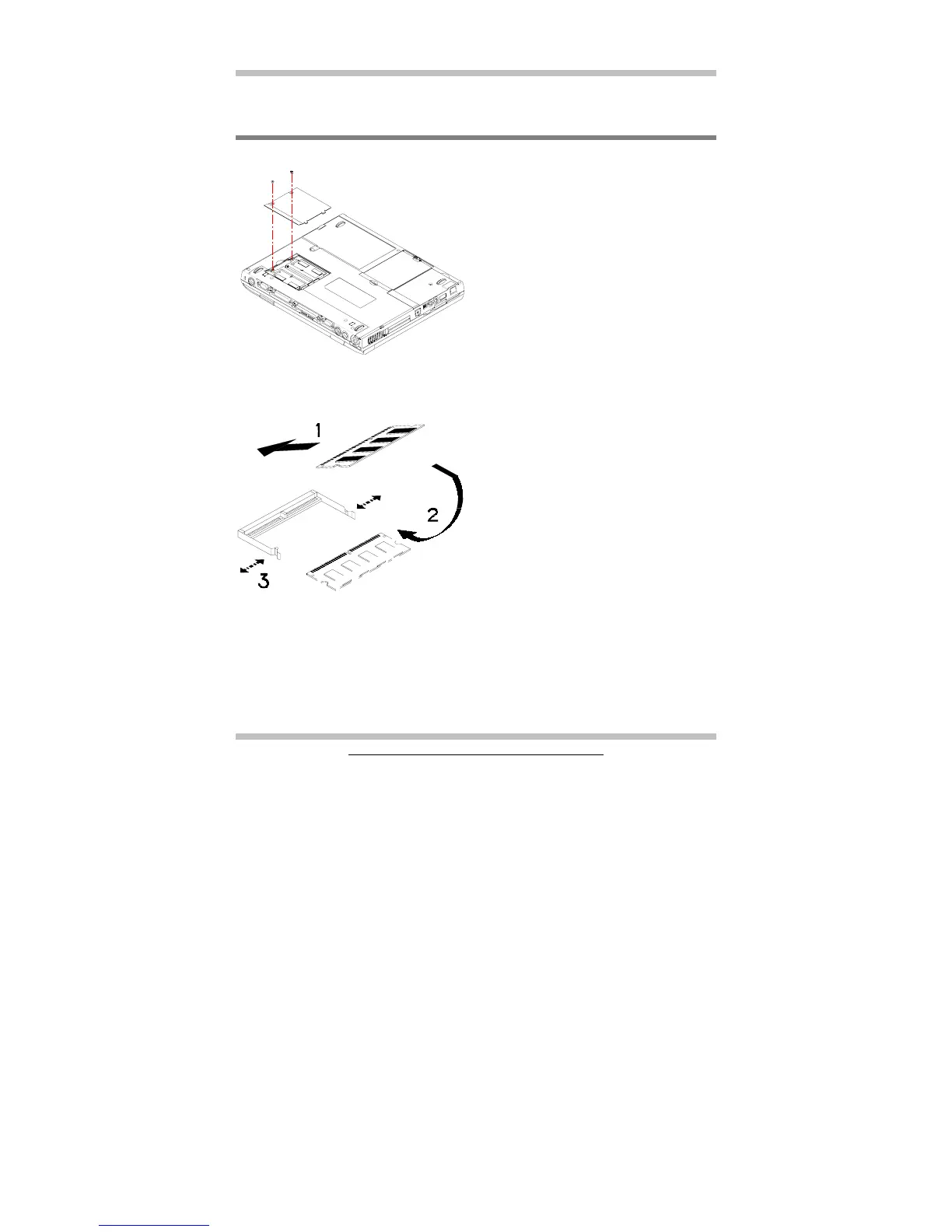
7.1 Inserting/Removing Memory Module
The diagram on the left shows where the
two memory sockets are located; and how
the compartment door is opened.
The diagram on the left shows the
procedure on how individual memory
modules be inserted into its socket:
• When inserting, the module should
have an angle of 45º with the
motherboard.
• Gently press the module down as
shown by arrow 2.
• You will hear a clicking sound when
the spring-locks (as shown by arrow
3) bent outward and then bend
inward to lock the memory module.