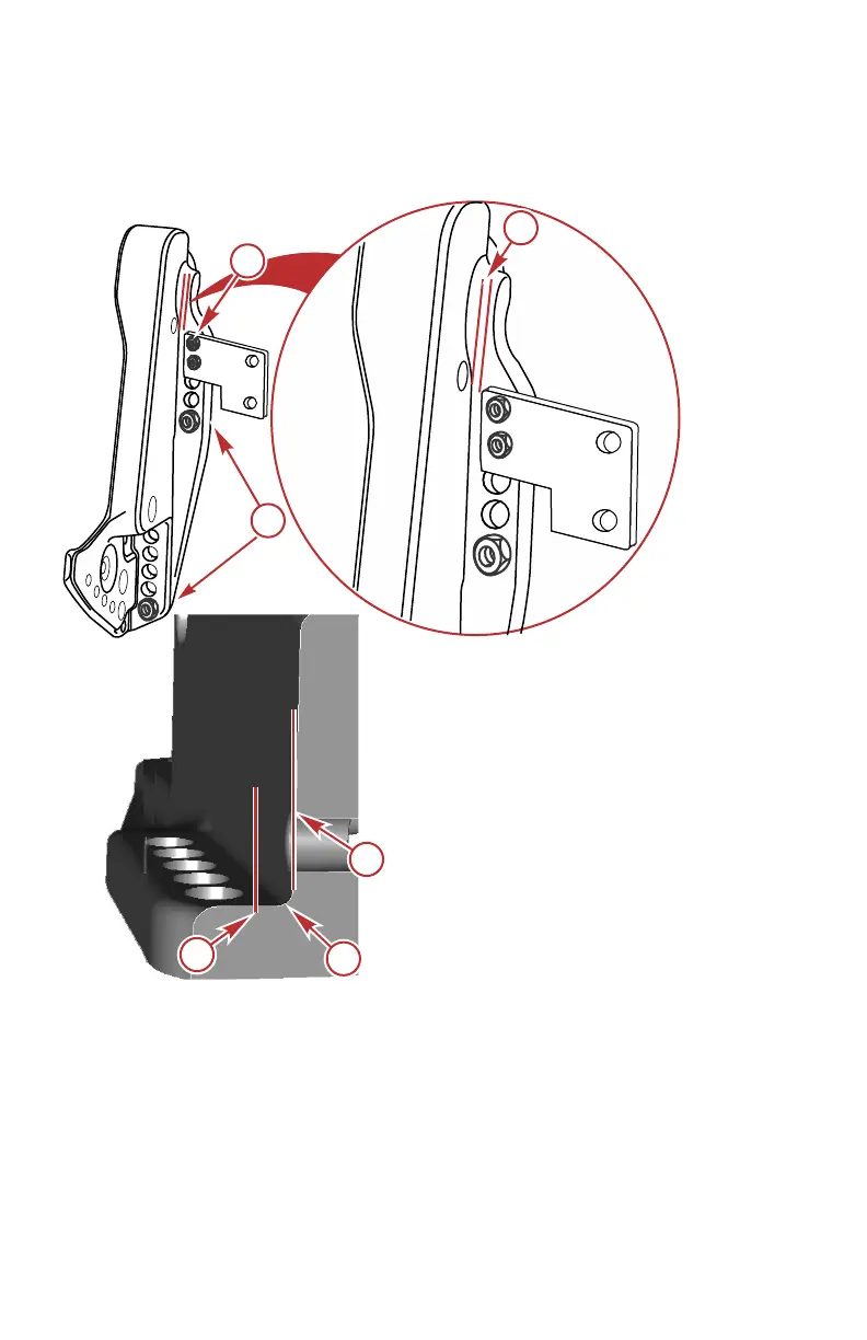
• The installation must not create interference issues, as would an
accessory mounting plate resting in the radius of the transom clamp
bracket. Refer to Figure 1.
Figure 1
a - Minimum clearance 3.175 mm (0.125 in.)
b - Edge of accessory bracket
c - Transom clamp bracket wall
d - Radius
e - Engine supplied mounting fasteners
f - Fasteners supplied by the accessory manufacturer installed through
unused engine mounting bracket holes
OUTBOARD INSTALLATION
116 eng
 Loading...


