GENERAL SYSTEM DIAGNOSTICS
SERVICE MANUAL NUMBER 23
90-861326--1 MARCH 1999 Page 5E-57
Chart A-1 (1 of 4): No Malfunction Indicator Lamp (MIL) -
Marine Diagnostic Trouble Code (MDTC) Tool Installed
461 ORN/BLK
451 WHT/BLK
a
b
c
d
e
f
g
h
i
j
k
l
m
n
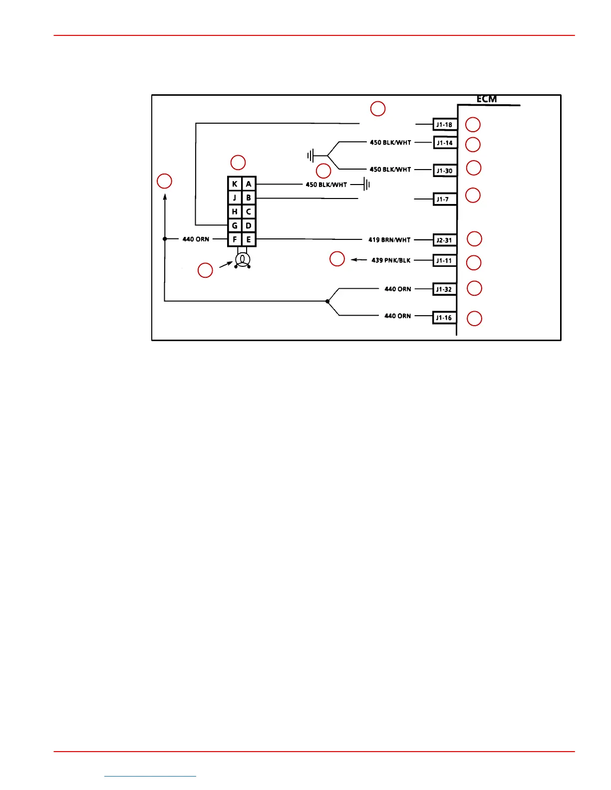
a-ECM/DLC 15amp fuse
b-DLC Connector
c-Marine Diagnostic Code Tool
d-ECM, Injector Knock Sensor Module 10amp Fuse
e-(ORN-Some Models)
f-(BLK-Some Models)
g-Serial Data
h-ECM Ground
i-ECM Ground
j-Diagnostic Test Terminal
k-Malfunction Indicator Lamp
l-Ignition Feed
m-Battery Feed
n-Battery Feed
CIRCUIT DESCRIPTION:
When the Marine Diagnostic Trouble Code (MDTC) tool is installed, it plugs into the DLC
terminals “F” and “E”. It receives voltage through CKT 440 terminal “F”
s Terminal “E” is
ground through CKT 419 from the ECM terminal “J2-31”. There should always be a steady
MIL with the ignition “ON” and the engine stopped. The Engine Control Module (ECM) turns
the MIL“ON” by grounding the MIL driver circuit.
Downloaded from https://needmanual.com/!

 Loading...
