INSTALLATION MANUAL
90-864198020 Page 37 of 77
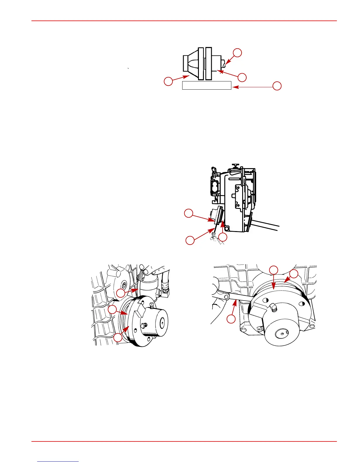
NOTE: Some propeller shaft couplers may not have a shoulder on mating face. On these
installations, use a straight edge to check centerline alignment.
74483
c
d
b
a
a-Transmission Output Flange
b-Propeller Shaft Coupler
c-Propeller Shaft
d-Straight Edge
4. Check for angular misalignment by hand holding coupling faces tightly together and
checking for a gap between coupling faces with a .003 in. (0.07 mm) feeler gauge. Check
the gap at 90 degree intervals.
75534
a
b
c
Velvet Drive
50608
a
a
b
b
c
c
50609
ZF / Hurth
a-Propeller Shaft Coupler
b-Feeler Gauge
c-Transmission Output Flange

 Loading...