Do you have a question about the Mercury MerCruiser 3.0 MPI and is the answer not in the manual?
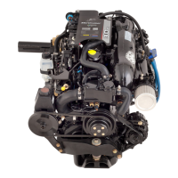
| Compression Ratio | 9.4:1 |
|---|---|
| Cylinders | 4 |
| Displacement | 3.0L / 181 CID |
| Fuel System | Multi-Port Fuel Injection (MPI) |
| Ignition System | Electronic |
| Fuel Type | 87 Octane |
| Full Throttle RPM | 4400-4800 RPM |
| Cooling System | Water Cooled |
| Exhaust | Water Cooled |
| Power Output | 135 HP @ 4800 RPM |
Specifies torque values for various fasteners to ensure secure installation.
Details methods and products to protect the power package from galvanic corrosion.
Provides precautions for applying anti-fouling paint to avoid warranty issues.
Describes the tamper-resistant label with engine emission and serial number data.
Outlines operator duties for maintaining emission levels and engine specifications.
Specifies critical dimensions for transom thickness and flatness for sterndrive mounting.
Details specifications for the engine mount alignment and placement.
Provides critical safety information regarding carbon monoxide hazards in boat exhaust.
Outlines the procedure to measure exhaust elbow height to prevent water intrusion.
Lists requirements for boats when performing exhaust elbow waterline height measurements.
Details how to load the boat to simulate conditions for waterline height measurements.
Specifies requirements for using low-permeation fuel hose for California compliance.
Provides guidelines for designing a safe and efficient fuel delivery system.
Lists specifications for sterndrive seawater pump output based on gear ratio.
Illustrates water flow paths for models with seawater cooling systems.
Shows water flow diagrams for models equipped with a closed cooling system.
Details procedures for cutting the transom to accommodate the drive unit.
Provides methods for locating the engine's vertical crankshaft centerline.
Explains using a 90-degree tool to determine the crankshaft horizontal center line.
Guides the installation of the gimbal housing onto the transom assembly.
Details how to connect the speedometer pickup hose to the drive unit.
Provides instructions for connecting the power trim pump's electrical system.
Explains the procedure for installing and adjusting the sterndrive shift cable.
Covers the final steps for installing the Alpha sterndrive unit.
Provides guidelines and specifications for selecting and installing a marine battery.
Outlines essential precautions to avoid damage when working with the electrical system.
Guides the selection and installation of boat harnesses for MPI sterndrive engines.
Details the connection and function of the key switch assembly.
Explains the function and connection of the lanyard stop switch for engine shutdown.
Describes how to connect an accessory relay for increased power supply.
Covers the installation of the Analog Gauge Interface for analog or SmartCraft gauges.
Explains how to configure the PCM for analog or digital tachometer signals.
Provides information and warnings regarding the installation of steering helm and cable.
Details critical dimensions and specifications for steering cables.
Guides the installer through checking and adjusting the Alpha sterndrive shift cable.
Offers solutions for common hard shifting or chucking/ratcheting issues.
Outlines final steps to prepare the power package for customer delivery.
Details procedures for checking and filling engine oil levels.
Provides instructions for checking and filling the power steering fluid reservoir.
Covers procedures for checking and purging air from the power trim pump system.
Explains the procedure for flushing the engine's cooling system with fresh water.
Details the use of flushing attachments for sterndrive water pickups.
Recommends procedures for preparing the engine for cold weather or storage.
Provides instructions for draining the engine's seawater cooling system.
A checklist of items to inspect and test before delivering the boat.


 Loading...