DRIVE SYSTEM AND ENGINE INSTALLATION SECTION - 6
Page 6 / 54 90-899883183 DECEMBER 2007
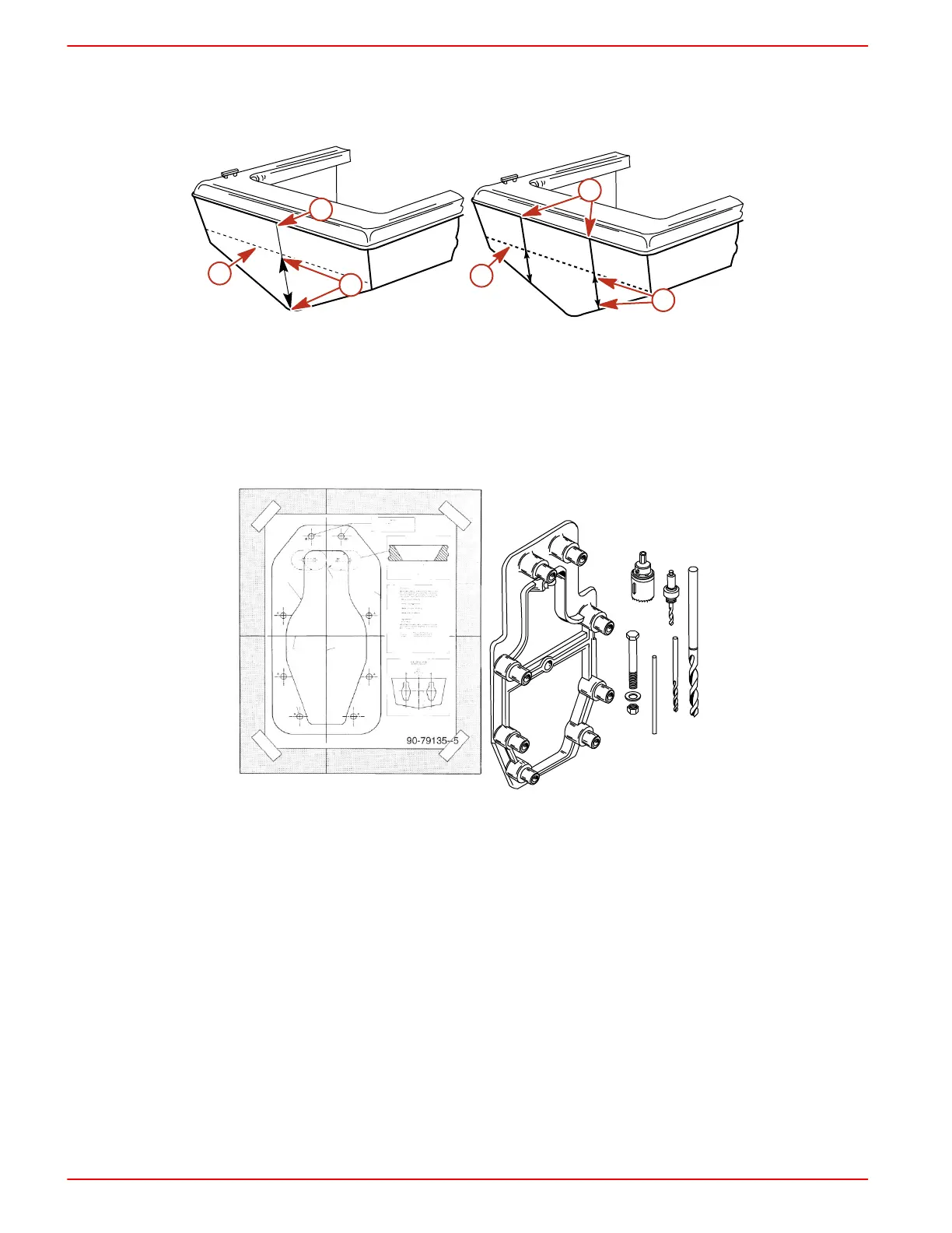
2. On the vertical crankshaft center line, measure up from the bottom of the transom to the
X‑dimension selected previously. This is the crankshaft horizontal center line at the
X‑dimension.
3. Draw a line perpendicular to the vertical center line at the crankshaft horizontal center line.
7692
c
a
b
7693
a
b
c
Single engine Dual engine
a - Vertical center line
b - X‑dimension that corresponds to
transom angle
c - Crankshaft horizontal center line
Cutting Out The Transom
1. Cut out transom using the Template or the Transom Drilling Fixture Kit (purchased separately).
7694
Transom cutout template Transom drilling fixture kit
2. Follow instructions indicated on template or provided with drilling fixture.
3. Ensure that centerlines on either the template or transom drilling fixture align with lines
previously marked on transom.
4. Drill two 6 mm (1/4 in.) pilot holes at a 60 degree angle for hole saw guides.

 Loading...
