PREDELIVERY PREPARATION AND STORAGE SECTION - 9
Page 22 / 24 90-899883183 DECEMBER 2007
14. If water is draining from the blue drain hose, continue with Step 4 of Single Point Drain
System.
Draining the Sterndrive
NOTE: This procedure is needed only for salty, brackish, mineral laden, or polluted water
applications; and for freezing temperatures or extended storage.
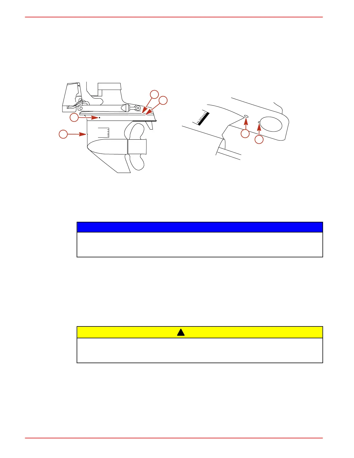
1. Insert a small wire repeatedly to make sure that vent holes, water drain holes, and passages
are unobstructed and open.
b
a
d
e
f
c
6146
Sterndrive Water Drain Holes
a - Speedometer pitot tube
b - Trim tab cavity vent hole
c - Trim tab cavity drain passage
d - Gear housing water drain hole (one
each at port and starboard)
e - Gear housing cavity vent hole
f - Gear housing cavity drain hole
NOTICE
The universal joint bellows may develop a set when stored in a raised or up position, causing
the bellows to fail when returned to service and allowing water to enter the boat. Store the
sterndrive in the full down position.
2. Lower the sterndrive to the full down/in position.
3. For additional assurance against freezing and rust, after draining, fill the cooling system with
propylene glycol mixed to the manufacturer's recommendation to protect the engine to the
lowest temperature to which it will be exposed during freezing temperatures or extended
storage
Power Package Recommissioning
1. Ensure that all cooling system hoses are connected properly and hose clamps are tight.
!
CAUTION
Disconnecting or connecting the battery cables in the incorrect order can cause injury from
electrical shock or can damage the electrical system. Always disconnect the negative (‑) battery
cable first and connect it last.
2. Install a fully‑charged battery. Clean the battery cable clamps and terminals and reconnect
cables (see CAUTION listed above). Tighten each cable clamp securely when connecting.
3. Coat the terminal connections with a battery terminal anti‑corrosion agent.
4. Perform all the checks in the BEFORE STARTING column of the Operations Chart.

 Loading...
