SECTION - 6 DRIVE SYSTEM AND ENGINE INSTALLATION
90-899883183 DECEMBER 2007 Page 5 / 54
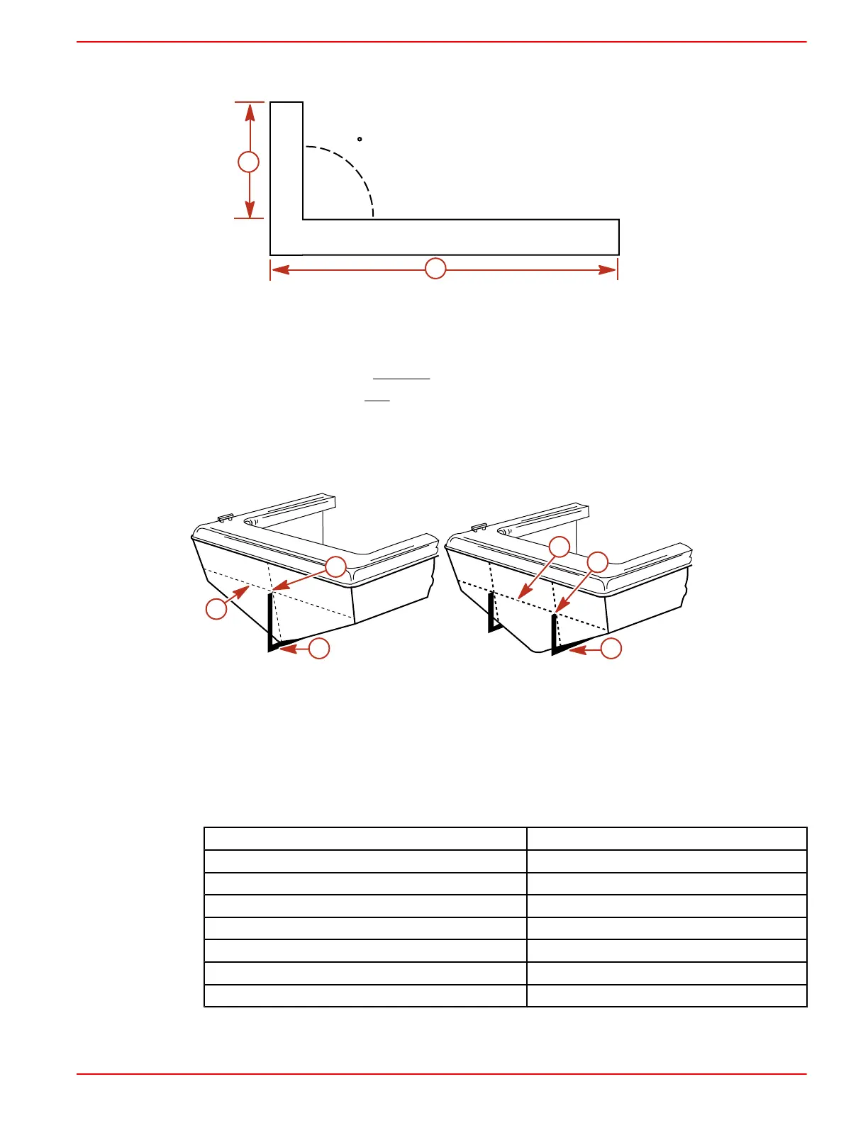
90 DEGREE TOOL METHOD
1. Construct the 90 degree tool.
90
a
b
7689
a - 34.5 cm (13‑9/16 in.) b - 1.2 m (4 ft)
IMPORTANT: The 34.5 cm (13‑9/16 in.) dimension should only be raised or lowered after proper
testing.
• ‑To lower drive unit - Subtract from dimension "a".
• To raise drive unit - Add to dimension "a".
2. Place the 90 degree tool along the boat bottom at the vertical center line.
3. Locate the point at which top of the 90 degree tool contacts the transom on the vertical center
line. This is the crankshaft horizontal center line or X‑dimension.
4. Draw a line perpendicular to the vertical center line at the crankshaft horizontal center line.
7690
b
c
a
7691
c
b
a
Single engine Dual engine
a - 90 degree tool along boat bottom at
vertical center line
b - Contact point
c - Crankshaft horizontal center line
TAPE MEASURE METHOD
1. Determine the X‑dimension from the following chart.
IMPORTANT: This dimension should only be raised or lowered after proper testing.
Transom Angle (degrees)
X‑dimension
16 36.4 cm (14‑5/16 in.)
15 36.2 cm (14‑1/4 in.)
14 36.0 cm (14‑3/16 in.)
13 35.9 cm (14‑1/8 in.)
12 35.7 cm (14‑1/16 in.)
11 35.6 cm (14 in.)
10 35.4 cm (13‑15/16 in.)

 Loading...
