SECTION - 6 DRIVE SYSTEM AND ENGINE INSTALLATION
90-899883183 DECEMBER 2007 Page 9 / 54
6. Secure the transom assembly with the hardware as shown. Torque the hardware.
Description Nm lb. in. lb. ft.
Transom assembly hardware 34 25
IMPORTANT: Tighten the transom assembly fasteners using an X‑pattern torque sequence,
starting from the middle fasteners. Tighten in small increments and go around the pattern several
times until the proper torque is achieved.
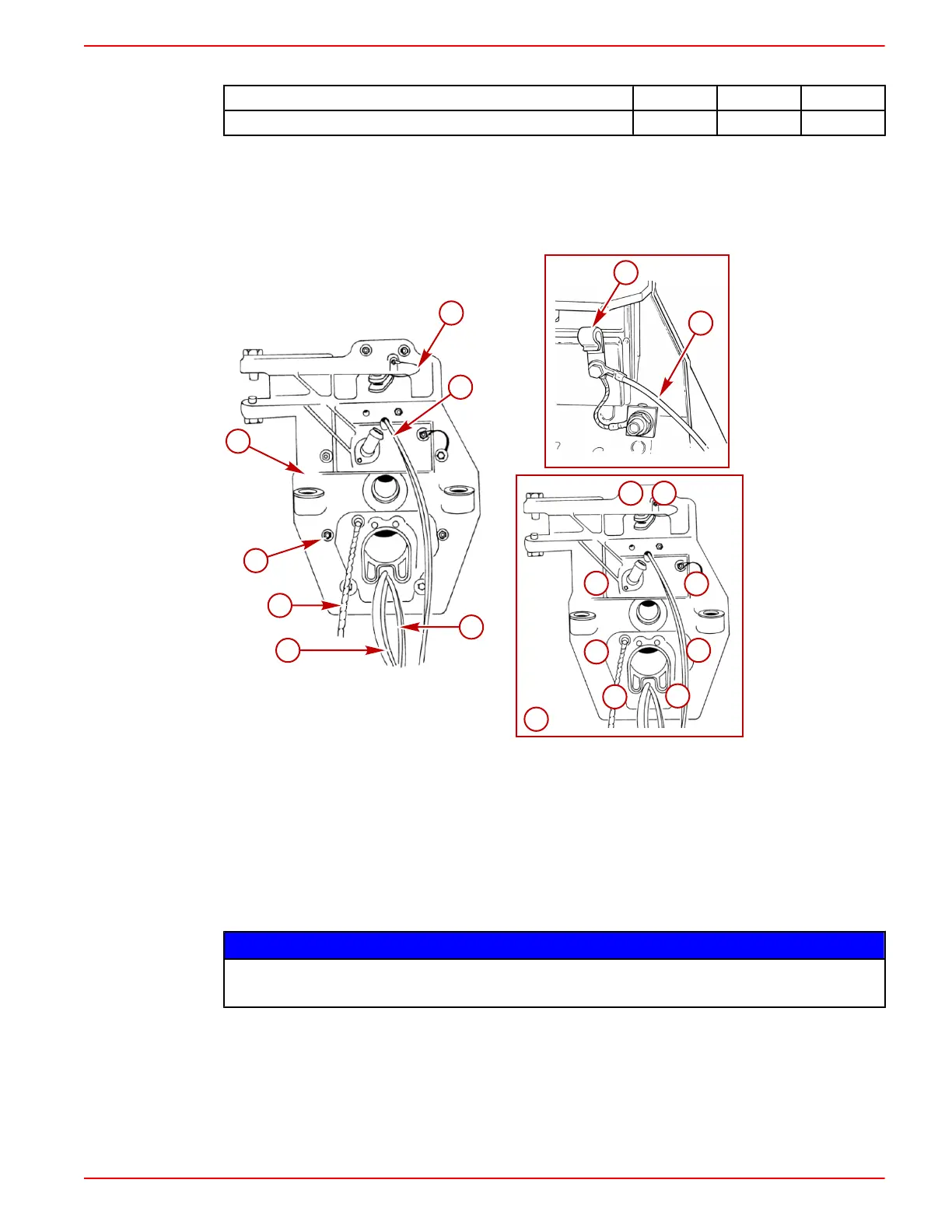
IMPORTANT: Steering lever continuity circuit wire must be positioned as shown to avoid stressing
wire when steering lever moves.
a - Locknuts and flat washers (8)
b - Hydraulic hoses
c - Drive unit shift cable
d - Trim limit and trim position sender
wires
e - Inner transom plate
f - Transom harness ground wire
g - Mercathode wires (if equipped)
h - J‑clip
i - Torque sequence
j - Steering lever continuity circuit wire
Connecting Speedometer Pickup
NOTICE
Removing the plug from the speedometer pickup fitting can introduce water into the bilge. Do
not remove the the plug unless you intend to make a connection to a speedometer pickup.
1. Remove the shipping cap from the male quick connect.

 Loading...
