SECTION - 6 DRIVE SYSTEM AND ENGINE INSTALLATION
90-899883183 DECEMBER 2007 Page 31 / 54
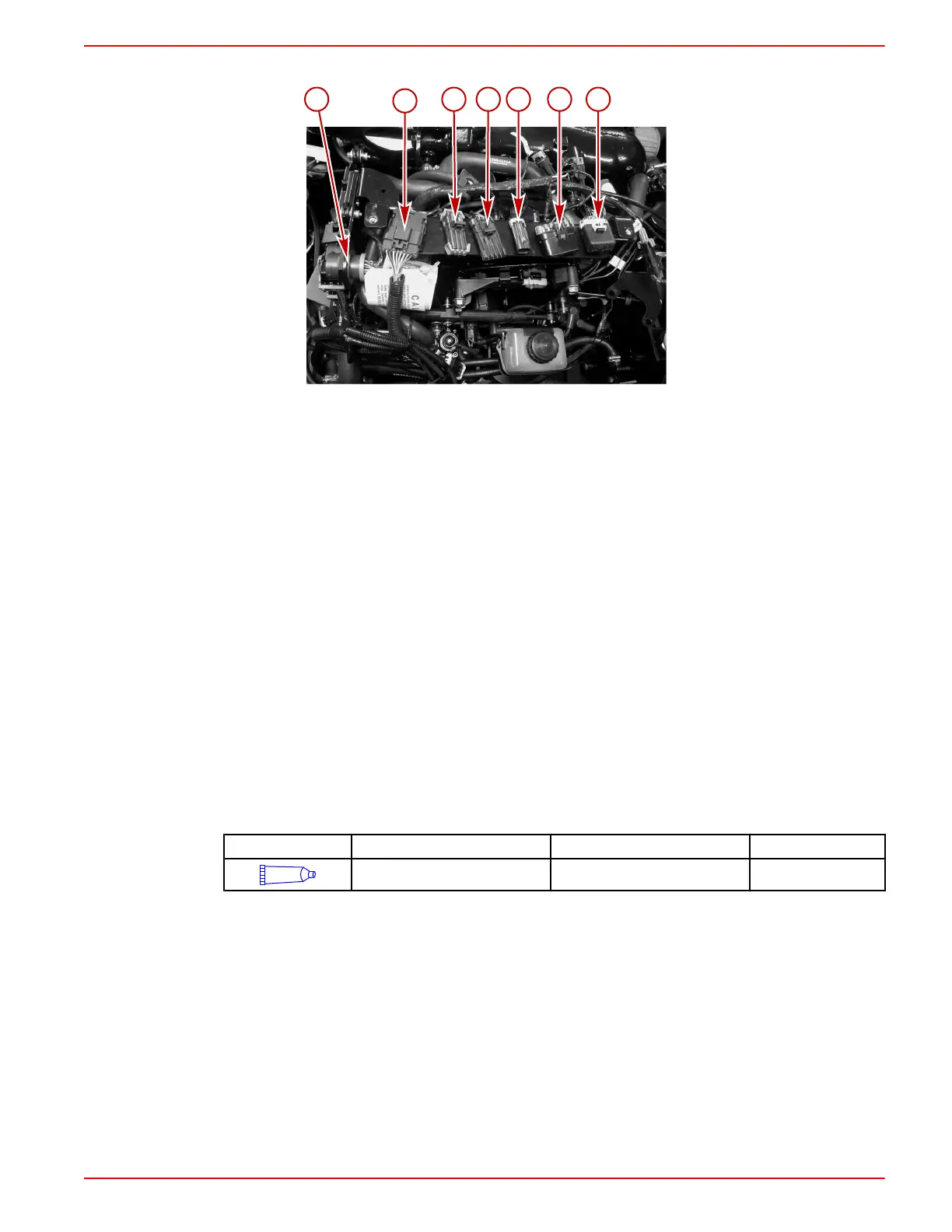
3. Connect the following:
a - 14‑pin harness connector
b - Transom harness connector
c - Paddle wheel and tank level
connector
d - Diagnostic connector
e - Power harness connector
f - Fuses
g - Fuses
CONTINUITY WIRE CONNECTION
IMPORTANT: The transom continuity circut is incorporated into the transom harness.
Electrical Connections
NOTE: Refer to Section 7 for additional electrical information.
To avoid damage to the electrical system, observe the following when working on or around the
electrical harness, or when adding other electrical accessories:
• Do not icorporate accessories into the engine harness.
• Do not probe or puncture wires for testing.
• Do not reverse the battery leads.
• Do not splice wires into the harness.
• Do not attempt diagnostics without the proper, approved service tools.
IMPORTANT: Route and secure all wires and hoses to avoid contact with hot spots and moving
parts.
Tube Ref No. Description Where Used Part No.
25
Liquid Neoprene All electrical connections 92- 25711 3
INSTRUMENTATION CONNECTIONS
We recommend using Quicksilver Instrumentation and Wiring Harnesses. On dual station
applications, oil pressure and water temperature senders on the engine must be changed. Refer
to the appropriate Mercury Precision Parts Accessories Guide for assistance.
The four basic gauges that must be used with the engine are:
• Tachometer
• Oil pressure
• Water temperature
• Voltmeter
NOTE: An accessory kit is available to provide accessory power up to 40 amps.

 Loading...
