SECTION - 7 STARTING AND ELECTRICAL
90-899883183 DECEMBER 2007 Page 21 / 22
Analog Gauge Type AGI Harness Wire Color
Fuel Level Pink/Black
GRY
PNK/BLK
BRN/WHT
TAN
BLU
a
c
d
b
f
e
3688
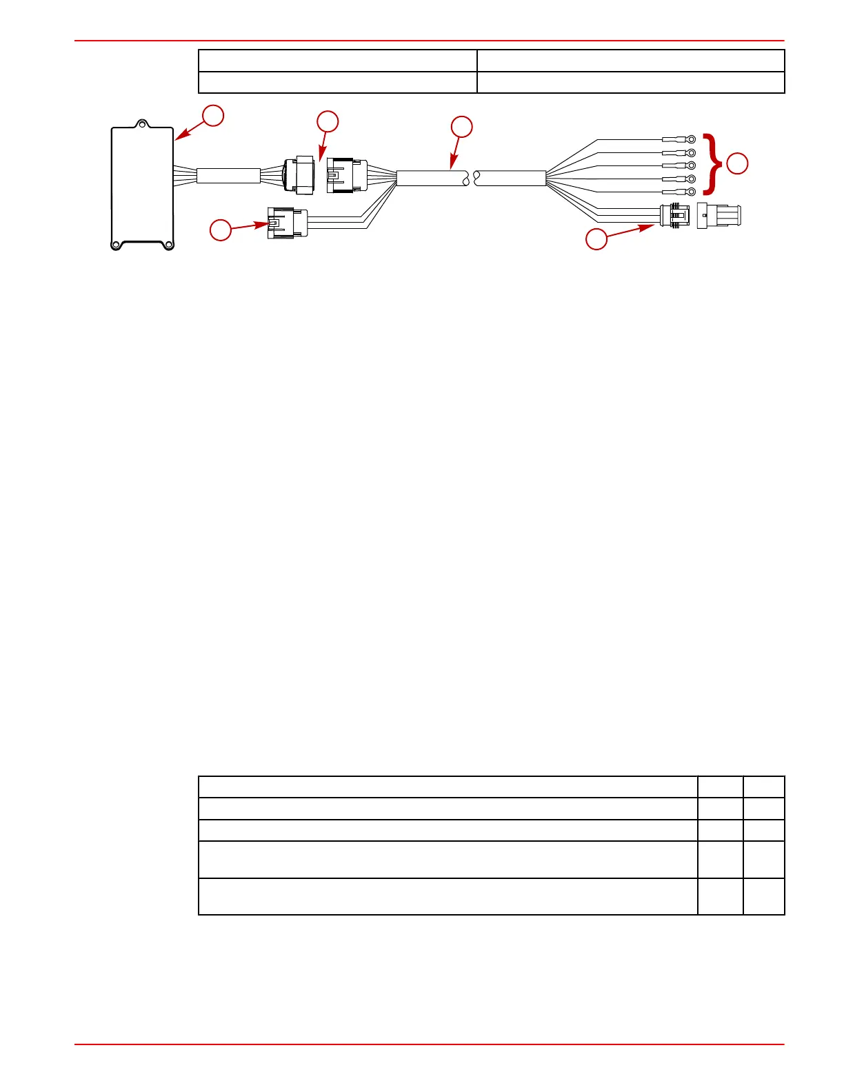
a - AGI module
b - 14 pin connection
c - AGI harness
d - Analog gauge terminal connections
e - System Link 3 pin connection
f - 10 pin CAN data connection
3. Route and connect the wire from the switched, 12 volt positive power source to the analog
gauges. Secure connections per gauge manufacturers' specifications.
4. Route and connect the ground wire from the analog gauges to a common ground. Secure
connections per gauge manufacturers' specifications.
5. Connect any SmartCraft System Link gauges to the 3‑pin System Link connection. The AGI
system can support 10 System Link gauges per helm, two helms maximum.
6. Plug the 14‑pin AGI harness connection into the AGI module.
7. Connect the 10‑pin CAN data harness connection on the command module harness to the
AGI harness.
a. Plug the10‑pin CAN data connection on the AGI harness directly into the 10‑pin CAN
data connection on the command module harness.
b. If the SmartCraft VesselView is used, a junction box and harness adaptor are required.
Plug the 10‑pin CAN data connection on the command module harness, the 10‑pin CAN
data connection on the VesselView harness, and one end of the harness adaptor into
the junction box. Plug the 10‑pin CAN data connection on the AGI harness into the other
end of the harness adaptor. Insulate any unused connection ports on the junction box
with weather caps.
Configuring Analog/Digital Tachometer Signal through PCM
IMPORTANT: The engine Propulsion Control Module (PCM) tachometer configuration factory
default has been set to an analog. This allows the operation of one analog tachometer. Depending
on the desired use of analog or digital gauges, the PCM setup may have to be configured from
analog to a digital.
Following are optional uses of analog and digital gauges and the setting for the tachometer
configuration in the PCM necessary to run them.
Gauge Configuration Analog Digital
Analog Tachometer Only
X
System Link Gauges used with VesselView, System Monitor, or System Tach
- -
System Link Gauges used in conjunction with System Link Adaptor Harness and Command
Module Harness without the use of VesselView, System Monitor or System Tach
X
AGI used with or without VesselView, System Monitor or System Tachometer, to run analog
and System Link Gauges
X
The Computer Diagnostic System (CDS) can communicate with the DTS command module.
However, the CDS will not configure TachLink Config‑Enable, which configures the PCM for using
an AGI and other special SmartCraft gauge configurations
To configure the PCM, contact the following Mercury MerCruiser representatives:

 Loading...
