SECTION - 6 DRIVE SYSTEM AND ENGINE INSTALLATION
90-899883183 DECEMBER 2007 Page 11 / 54
NOTE: The quick release button on hose fitting must be positioned away from water inlet fitting,
or block‑off plate if equipped. Release button must not contact water fitting or block‑off plate, if
equipped.
2. Position quick release button on hose fitting away from water inlet fitting. Release button must
not contact water fitting.
a
e
f
d
d
b
c
7705
Alpha transom
a - Water inlet fitting
b - Star washer and screw
c - 90 degree hose fitting
d - Quick release button
e - ACCEPTABLE positions
f - NOT ACCEPTABLE position
Description Nm lb. in. lb. ft.
Water inlet fitting bolts 5 45
NOTE: The hose must not come into contact with the steering system components or the engine
coupler and drive shaft.
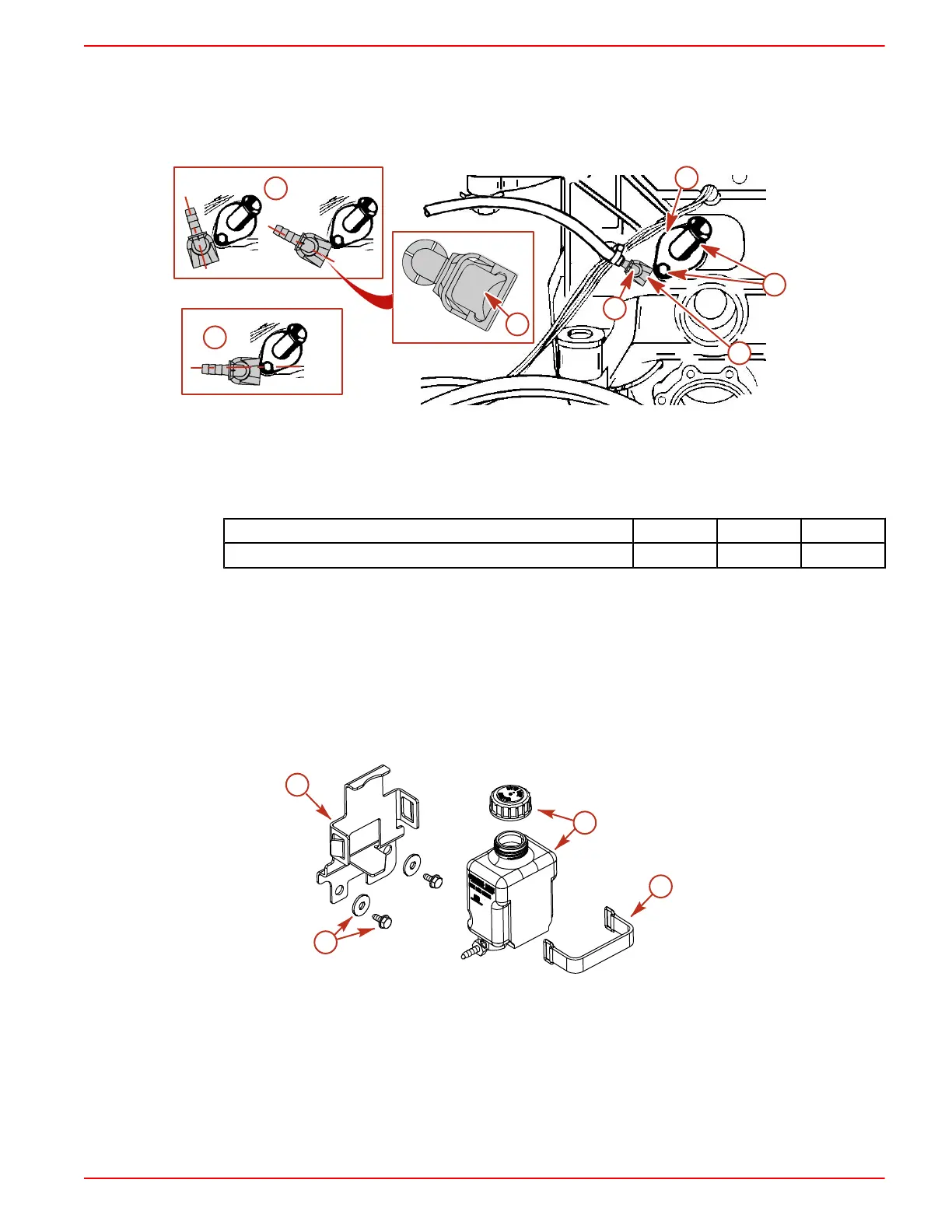
Alternative Mounting of Gear Lube Monitor on Transom
IMPORTANT: The mounting location specified must be above the steering lever on the transom
assembly. Hose must be positioned to avoid moving parts (steering system, engine coupler).
1. Install the gear lube monitor bracket in the specified location and secure with lag screws and
flat washers.
2. Install the gear lube monitor in the bracket. Secure the monitor with the retaining strap.
a
b
c
d
7706
a - Bracket
b - Lag screw and flat washer
c - Gear lube monitor and cap
d - Retaining strap
Power Trim Pump
1. Select an appropriate mounting location (floor or transom) for the trim pump that:
• Is within length limits of BLACK and GRAY hydraulic hoses coming from gimbal housing
assembly.

 Loading...
