DRIVE SYSTEM AND ENGINE INSTALLATION SECTION - 6
Page 10 / 54 90-899883183 DECEMBER 2007
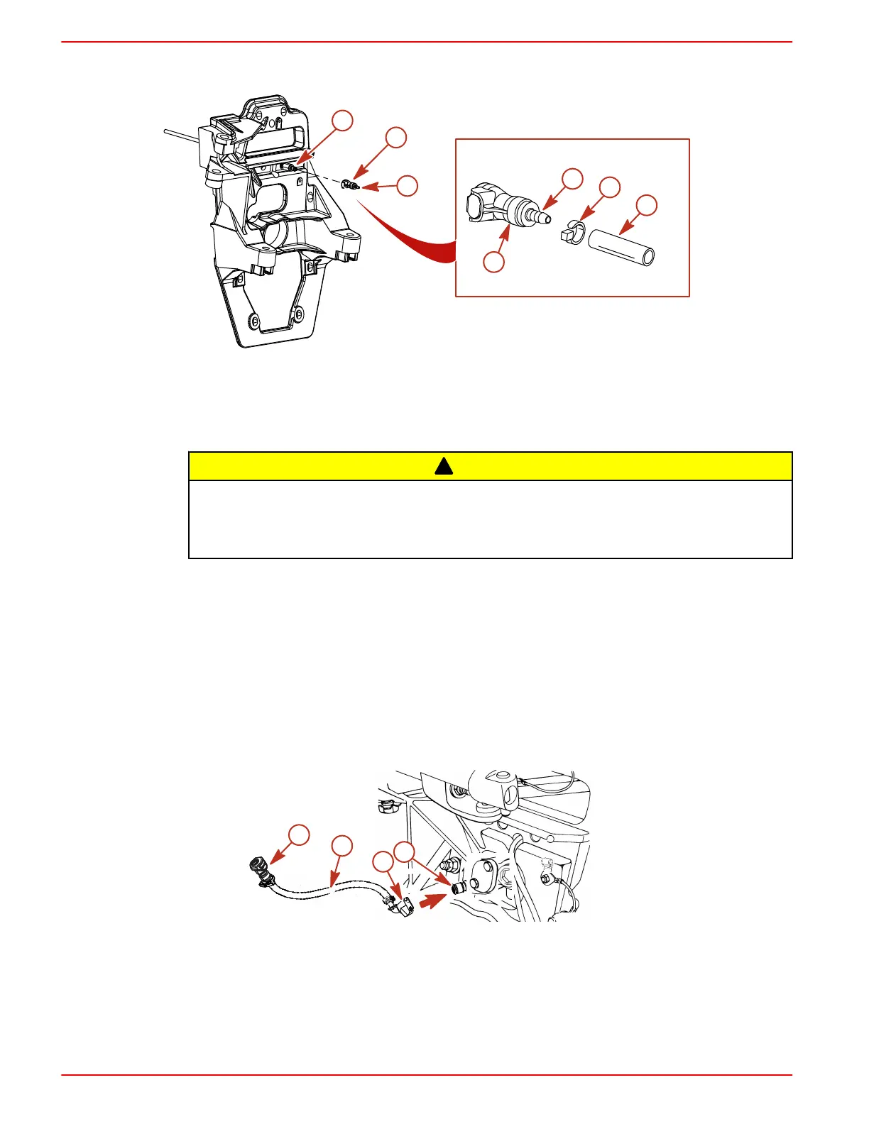
2. Connect a 4 mm (5/32 in.) speedometer hose (not provided) from speedometer to barb fitting.
Secure hose with tie strap.
a
b
c
7703
c
e
d
b
Typical
a - Male quick connect
b - Female quick connect
c - Barbed fitting
d - Hose
e - Tie strap
!
CAUTION
A ruptured speedometer hose can introduce water into the bilge, causing boat damage or
possible sinking. Position or install the speedometer hose away from moving parts or pinch
points, such as steering system components, engine coupler, or driveshaft, which could damage
the hose.
3. Secure the hose to the transom with the hose clip and screw that are provided in the parts
bag.
4. Ensure that the hose does not contact the steering system components or the engine coupler
and drive shaft.
NOTE: The hose must not come into contact with the steering system components or the engine
coupler and drive shaft.
Alpha Gear Lube Monitor Connection At Gimbal Housing
NOTE: The gear lube monitor hose is now in the parts bag on the engine.
1. Connect the quick release 90 degree fitting of the gear lube monitor hose to the gimbal
housing.
c
b
d
a
7704
a - Hose
b - Quick release 90 degree fitting
c - Gimbal housing fitting
d - Quick connect fitting

 Loading...
