SECTION - 6 DRIVE SYSTEM AND ENGINE INSTALLATION
90-899883183 DECEMBER 2007 Page 47 / 54
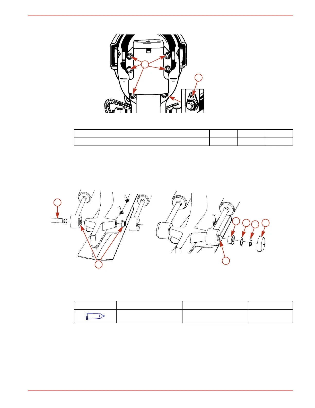
f. Secure the sterndrive to the bell housings using fasteners as shown. Torque the
fasteners to specifications.
b
a
7858
a - Locknut and flat washers b - Locknut and continuity circuit washer
Description Nm lb‑in. lb‑ft
Sterndrive unit fasteners 68 – 50
16. Return remote control shift lever to the neutral position.
TRIM CYLINDER INSTALLATION
1. Install the trim cylinders on the aft end of the sterndrive unit with hardware as shown.
2. Install the plastic caps by snapping in place.
NOTE: Lubricate all components except plastic caps during installation.
a
b
b
a
c
d
e
7849
a - Aft anchor pin
b - Bushings
c - Flat washers
d - E‑ring clips
e - Plastic caps
Tube Ref No. Description Where Used Part No.
95
2-4-C Marine Lubricant with
Teflon
Trim cylinder hardware 92-802859A 1
3. Install the sterndrive unit serial number decal.
Speedometer Connection
1. Raise drive to gain access to area between gimbal housing and sterndrive, immediately above
the transom end of the anti‑ventilation plate.
2. Align plastic slots on male and female portions and insert.

 Loading...
