INSTALLATION
90-888438 JUNE 2002 Page 1D-37
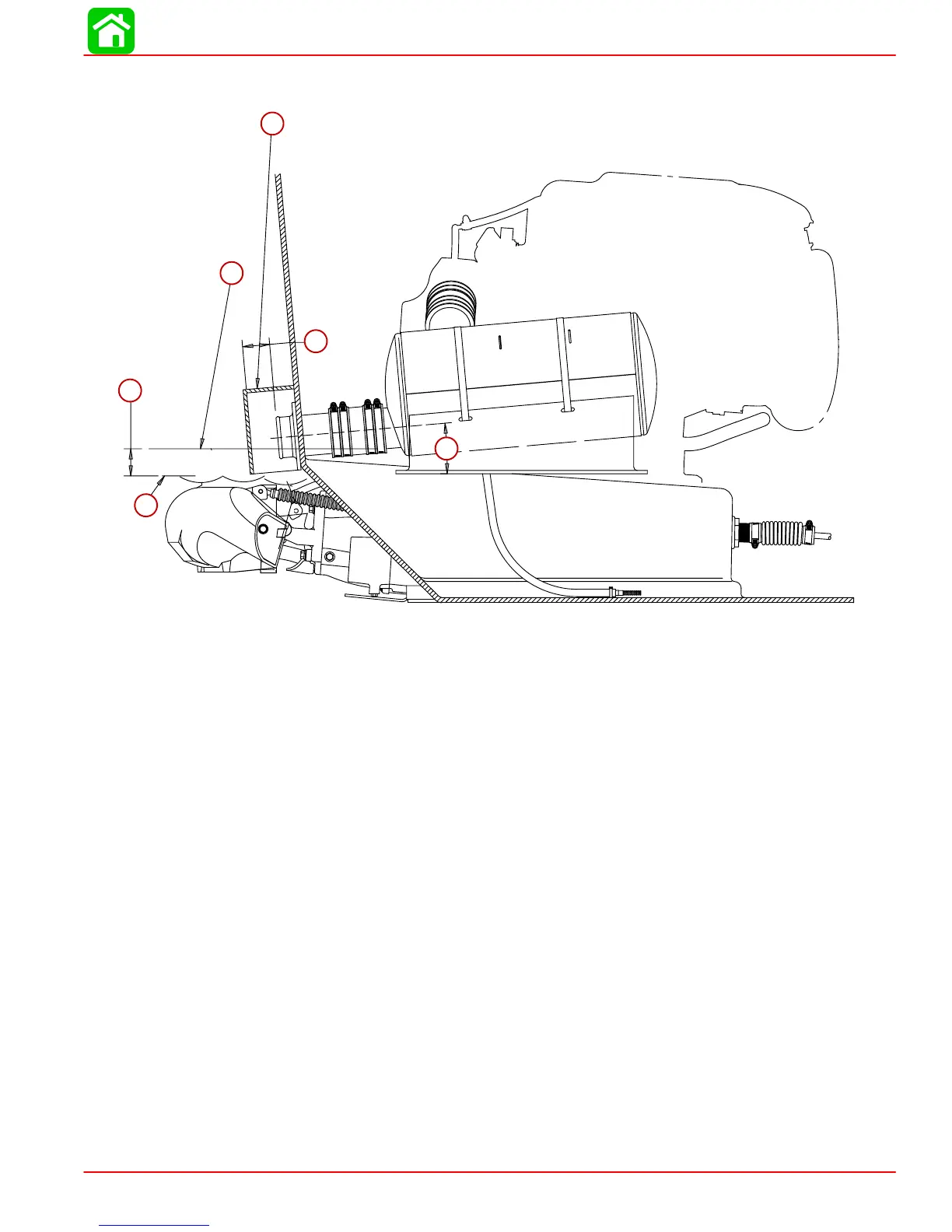
Side View
a
b
c
d
e
f
a-This line represents the bottom edge of the muffler outlet tube. Measure to en-
sure that the lowest possible location of the bottom edge of the muffler tubes
never gets within 2.0 in (5.1 cm) of the maximum depth waterline.
b-2.0 in (5.1 cm). When installing muffler assemblies, a 2.0 in (5.1 cm) minimum
distance between bottom of muffler and water line must be kept. This minimum
distance must be calculated with boat under its maximum load. Tilt muffler as-
semblies back towards outlet to ensure self draining.
c-Water Line
d-Covers may be placed over exhaust outlets to reduce exhaust noise and may
extend 5 in (10 cm) or less below waterline when boat is at rest.
e-2.0 in (5.1 cm).
f-5° outlet angle.
 Loading...


