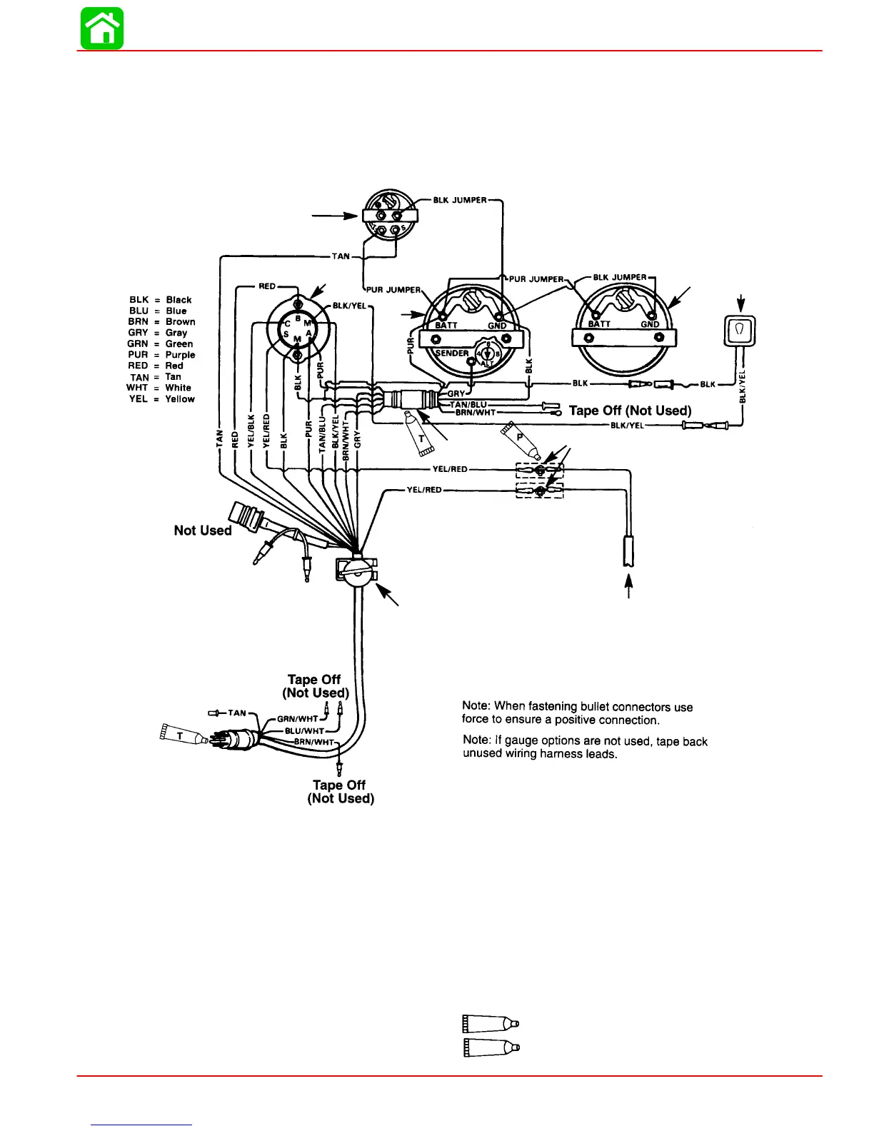
a - Temperature Gauge
b - Key Switch
c - Tachometer Gauge
d - Emergency Stop Switch
e - Tachometer Harness (P/N 84-86396A8) (Not Included
With Key/Choke Harness Kit)
f - Connect Wires Together With Screw and Hex Nut (2
Places) Apply Quicksilver Liquid Neoprene to Connections
and Slide Rubber Sleeve Over Each Connection.
g - To Neutral Start Safety Switch In Remote Control Box
Liquid Neoprene
Dielectric Grease
T
h - Speedometer Gauge
i - Overheat/low oil horn
a
b
c
d
e
f
g
h
i
P
INSTALLATION
90-888438 JUNE 2002 Page 1D-7
Wiring Diagrams
Quicksilver Instrumentation, Typical Analog Installation Shown
NOTE: Refer to gauge manufacturer’s instructions for specific connections.