14 Meritor Differential Carrier 17X
2 Maintenance
Introduction
In order to ensure reliable and efficient differential unit operation,
maintenance intervals, use of lubricants and correct procedures
specified by the manufacturer should be strictly observed (refer to
Lubrication Maintenance Manual no.1). For further information
contact the manufacturer’s engineering department or refer to the
Meritor Web site at www.meritor.com
Spare parts
Use original Meritor spare parts only.
Differential removal and installation
1. If the vehicle is loaded, unload the rear axle before removing
the differential.
2. Place the vehicle on level ground and chock the front wheels.
3. Rest the rear axle on two suitably strong axle stands.
4. Remove the drain plug from the rear axle bottom end and drain
lubricant.
5. Engage differential lock before air pressure falls below 2.8 bars
6. Remove axle shaft mounting screws and washers.
7. Remove axle shafts.
8. Remove propeller shaft.
9. Disconnect compressed air lines and differential lock sensor
switch coupling.
10.Remove differential carrier to rear axle housing fastening
screws (leave two screws in place to prevent the differential
from falling).
11.Safely support carrier assembly with suitable lifting tool to aid
removal. Remove plastic protective plugs fitted to the
extraction screw holes. Fit extractor screws. Remove final 2
carrier screws to withdraw carrier assembly. Mount the carrier
assembly in a suitable fixture and remove the differential lock
assembly as described in Section 5 Differential Lock
Removal.
Checking rear axle housing
Check rear axle alignment to prevent possible distortion from
causing abnormal stress, noise and pneumatic consumption.
Installation - Reassembly
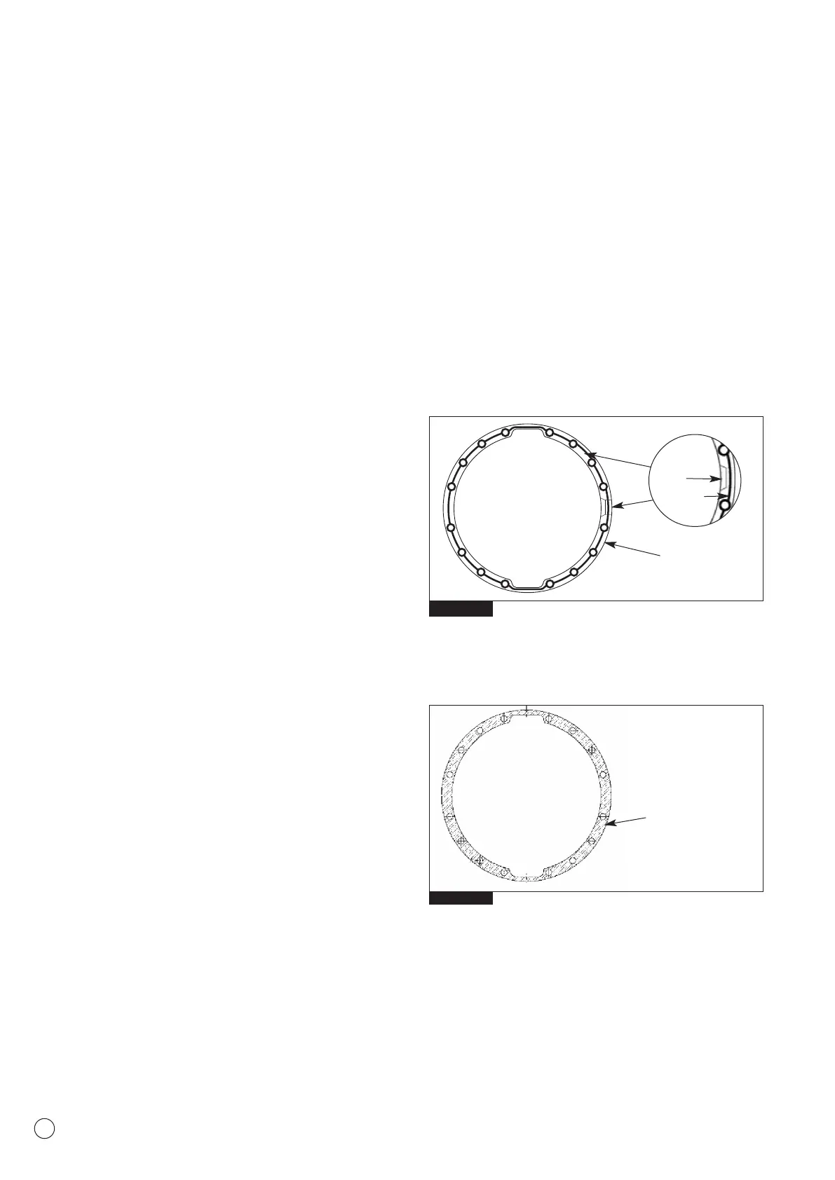
1. Clean mounting faces and threads thoroughly. Apply a
continuous bead of sealant DC 7091 to the rear axle mounting
face (Fig.2.1a) Ensure the continuous bead of sealant is applied
around the slots in the mounting face to achieve correct
sealing. DO NOT apply the sealant over the slots (Fig 2.1a).
2. Apply sealant (Loctite 510 or 549) to the complete surface of
the joint gasket (Fig 2.1b.)
NOTE: The carrier to housing assembly must be completed within
15 minutes of applying the sealant to the mating surfaces.
Reverse the removal operation sequence and torque fastening
screws/nuts and drain plug to the specifications detailed in
Section 6 Tightening Torques & Lubrication.
Fig. 2.1a
Fig. 2.1b
Continuous bead
of sealant
DC7091
Apply sealant
(Loctite 510 or 549)
to the complete surface
Slot
Sealant