23
Meritor Differential Carrier 17X
2 Maintenance
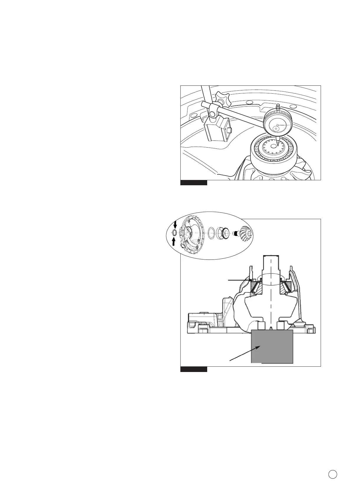
11. Set a DTI (Dial Test Indicator) against the head of the pinion
spigot nose and set to “0” (Fig.2.26).
12. Move the pinion shaft and measure the axial movement
recorded on the DTI. Record the measurement Y
13. Using the dimension of the master spacer X and the DTI
reading Y, calculate the correct spacer value required
following the calculation;
X - Y- 0.08mm (coefficient factor) = Spacer dimension
Example:
Master Spacer X = 15.155mm
Pinion Axial Movement Y = 0.55mm
Coefficient Factor = 0.08mm
15.155 - 0.55 - 0.08 = Calculated Spacer Value 14.525mm
NOTE: The spacers control the preload adjustment of the drive
pinion bearings. Always select a spacer as close as possible to
the value calculated.
14. Remove the pinion nut and flange.
15. Remove the outer bearing cone and master spacer.
16. Position the calculated spacer identified above to provide the
correct bearing pinion preload (Fig.2.27) and continue
assembling the carrier.
17. Using a suitable service tool (CT45), firmly press the outer
bearing cone of the pinion shaft once more against the
spacer/s (Fig.2.28) using a press load of 6 - 8 ton. Rotate the
pinion by hand to seat the bearings.
Fig. 2.26
Fig. 2.27
Wooden Block
Pinion Head Support
Calculated
Spacer