48 Meritor Differential Carrier 17X
5 Differential Lock Removal
The procedure detailed below provides a safe and efficient method
f
or removing the differential lock components without causing
damage to either the components or carrier.
1. Remove the carrier assembly from the vehicle as described in
Section 2, Maintenance and mount securely in a suitable
fixture.
2. Remove the four capscrews which secure the differential lock
cover to the carrier.
3. Remove the differential lock cover and gasket
NOTE: Never reuse the existing gasket. Always fit a new gasket
on reassembly.
4. Using a copper or plastic-faced hammer strike the outer face
of the differential lock fork. This action should eject the
differential lock piston sufficiently to allow removal from the
housing.
5. Remove the differential lock piston. (or new single push-rod).
6. While holding and manipulating the differential lock fork,
remove the shift shaft from the cylinder bore (or new single
push-rod).
7. Locate a suitable size diameter socket or sleeve, which is a
minimum of 52mm in length, into the cylinder bore so that it
abuts against the face of the differential lock fork.
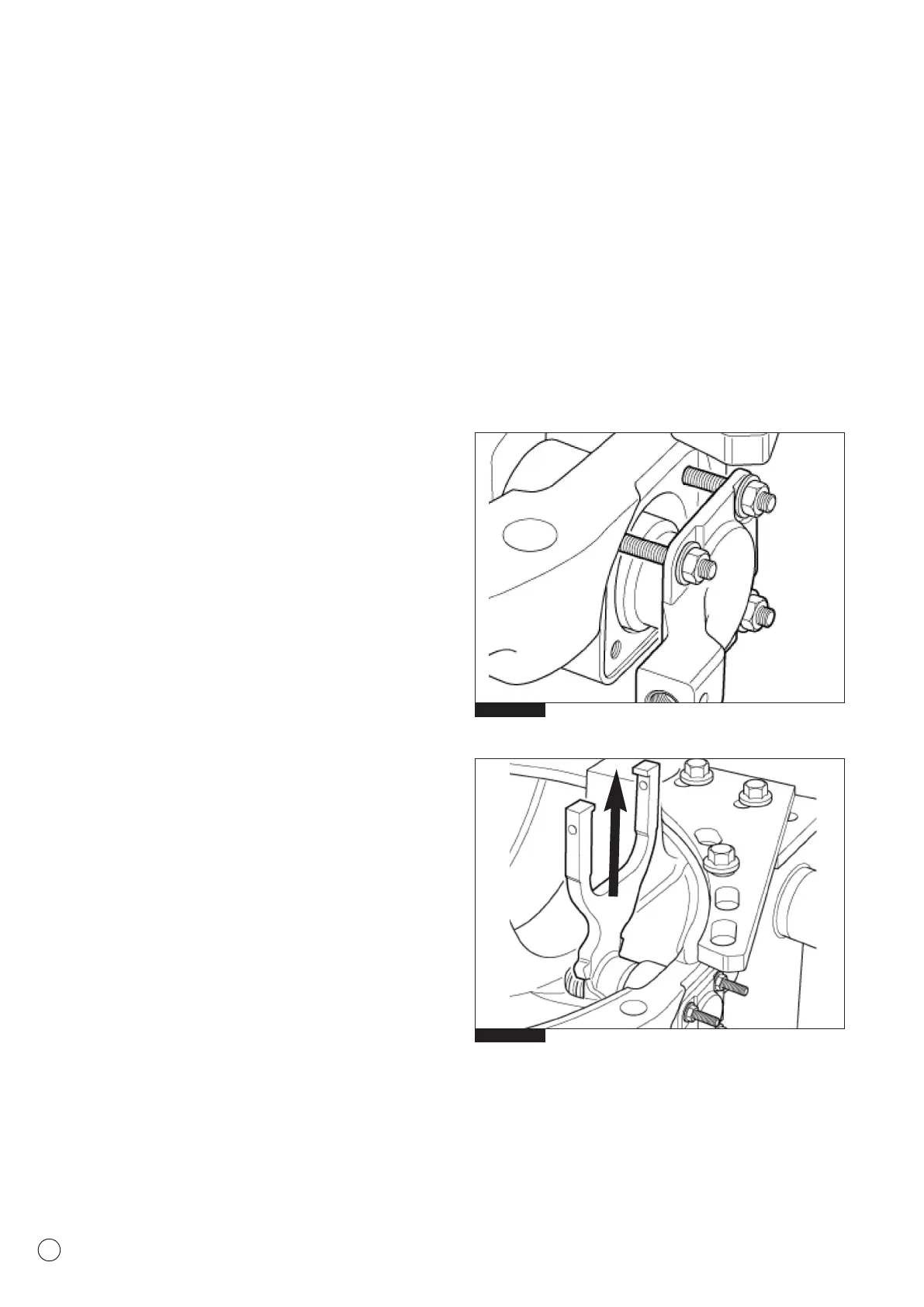
8. Refit the differential lock cover and secure in place against the
socket/sleeve with 4 M6 studs, washers and nuts, or M6 bolts
(Fig 5.1). The studs or bolts must be a minimum of 50mm
long.
9. Tighten the nuts/bolts evenly, ensuring the cover is kept
square to the carrier face. This action will compress the
differential lock fork and spring sufficiently to allow the
differential lock fork to clear the lug of the cylinder on the
carrier casting.
10. Carefully withdraw the differential lock fork and spring
complete from the carrier by pulling upwards (Fig 5.2).
11. Remove the differential lock cover, studs or bolts and
socket/sleeve from the carrier.
NOTE: Check that the differential lock spring has not been
damaged or distorted in any way during the removal procedure.
I
f there is a doubt in the suitability of any component for further
service, replace with new Meritor service parts.
12. Reassemble the differential lock assembly as described in
Section 2, Maintenance.
Fig. 5.2
Fig. 5.1