24 Meritor Differential Carrier 18X
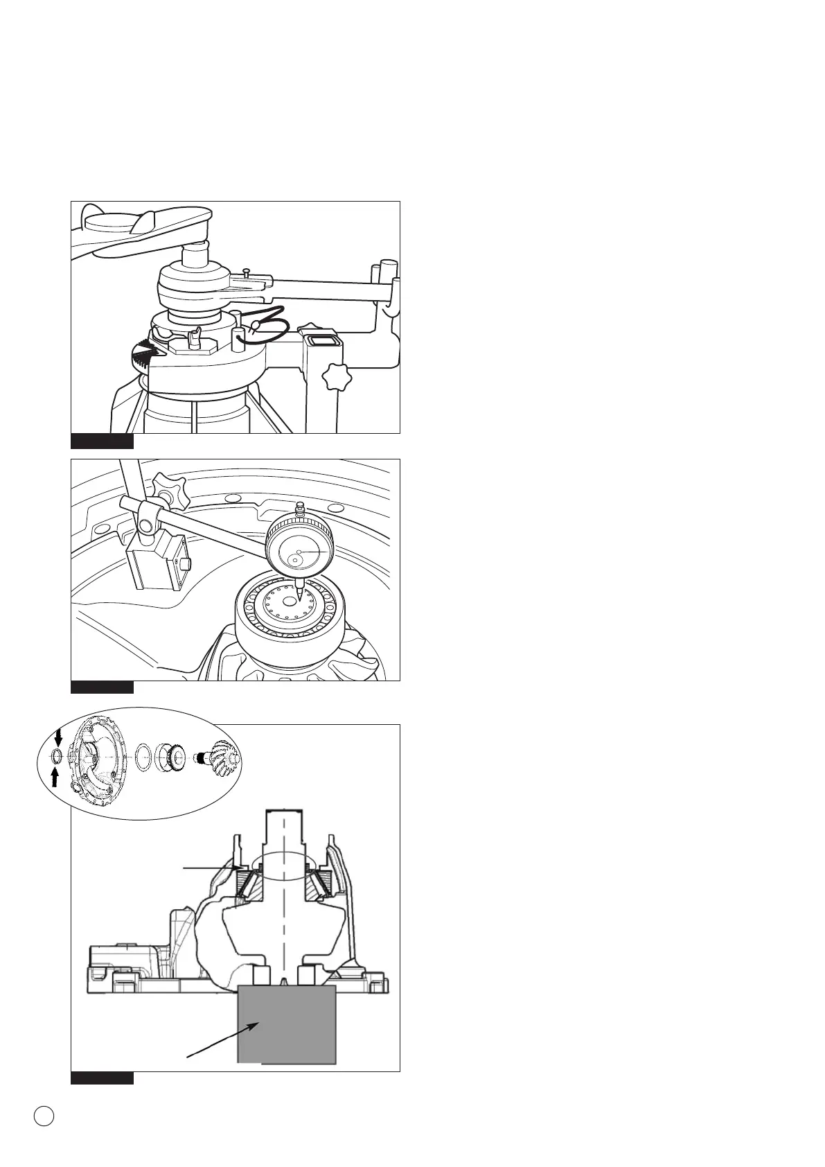
13. Set a DTI (Dial Test Indicator) against the head of the pinion
spigot nose and set to “0” (Fig.2.30).
14. Move the pinion shaft and measure the axial movement
recorded on the DTI. Record the measurement Y
15. Using the dimension of the master spacer X and the DTI
reading Y, calculate the correct spacer value required
following the calculation;
X - Y- 0.08mm (coefficient factor) = Spacer dimension
Example:
Master Spacer X = 23.510mm
Pinion Axial Movement Y = 0.55mm
Coefficient Factor = 0.08mm
23.510 - 0.55 - 0.08 = Correct Spacer Value 22.88 mm
NOTE: The spacers control the preload adjustment of the drive
pinion bearings. Always select a spacer as close as possible to
the value calculated
16. Remove the pinion nut and flange.
17. Remove the outer bearing cone and master spacer.
18. Position the calculated spacer identified above to provide the
correct bearing pinion preload (Fig.2.31) and continue
assembling the carrier.
Fig. 2.30
Fig. 2.31
Wooden Block
Pinion Head Support
Calculated
Spacer
Fig. 2.29
2 Maintenance
NOTE: Lubricate the surface of the Flange Nut and
Companion Flange.
Oil the threads.
Tighten flange lock nut to a torque of 2000 - 2500 Nm.
(Fig. 2.29)