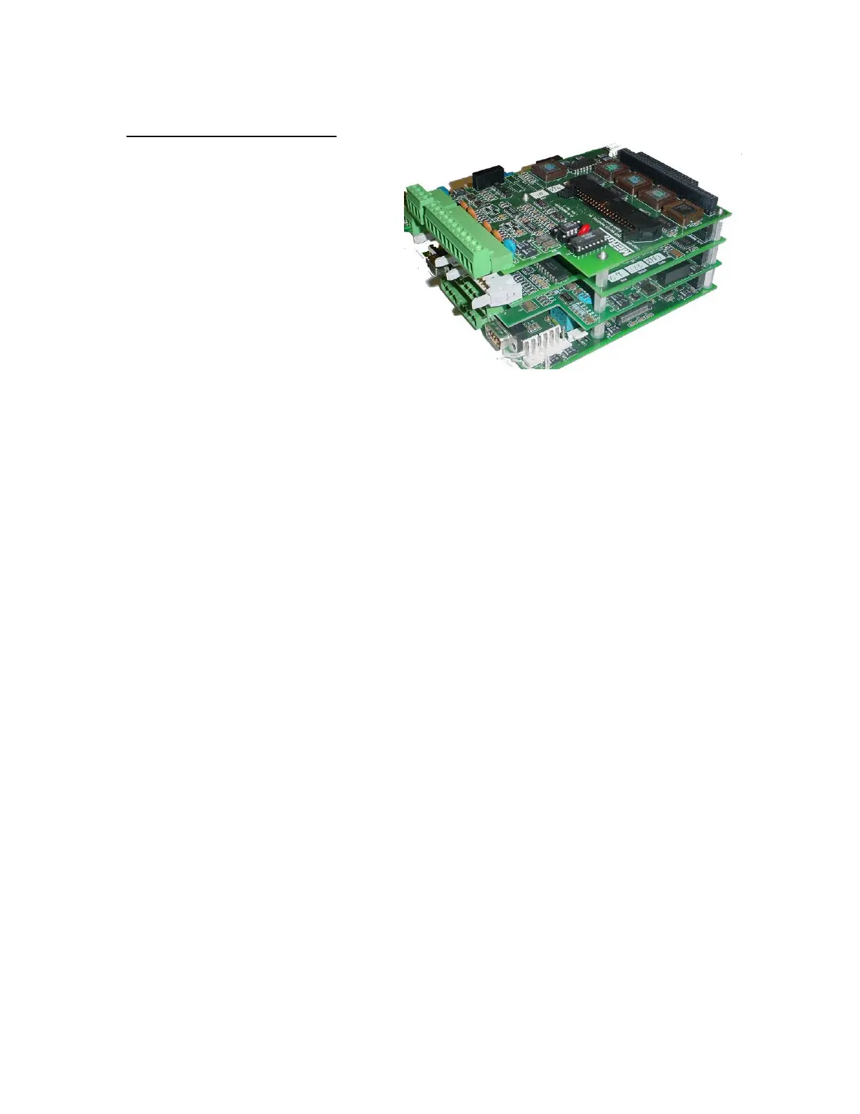
CARD STACK ASSEMBLY
The Card Stack is a grouping label for the
primary boards of the controller which
consists of one (1) CPU Board, one (1) or
two (2) HPAD boards, one (1) or two (2)
PCIO boards and one (1) LTI board. The
Card Stack Assembly in the panel mount
enclosure is mounted to the slide tray. The
slide tray is kept in place by a pair of
guides that are mounted on the enclosure
and with catch screws on the back of the
enclosure. In the wall mount and door
mount enclosures; the Card Stack
Assembly is securely attached to the
mounting plate. All boards are connected
electronically by way of an industry
standard PC-104 interface bus.
CONNECTIONS
The MC³ is capable of processing many different types of inputs and outputs. Most of the
connections necessary for the inputs and outputs are located on the Backplane Boards which are
plugged into the PCIO boards at the connectors labeled “Racks”. The diagram below shows the
card stack as seen from the back, with additional optional boards in the card stack. If an older
revision CPU is present, then the diagram on the following page should be used.
MC3 Hardware Manual 8

 Loading...