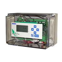
PCIO BOARD
The PCIO Board provides the circuitry for two (2) isolated
analog outputs; one (1) isolated analog input, sixteen (16)
digital outputs and eight (8) digital inputs. An additional
PCIO Board is available as an option giving the controller a
capability of having four (4) isolated Analog Outputs, two (2)
isolated Analog Inputs, thirty-two (32) Digital outputs and
sixteen (16) Digital inputs. Two (2) racks of digital inputs
and outputs can be connected to one (1) PCIO board or
four (4) can be connected if there are two (2) PCIO Boards.
Located on the left side of the board, as pictured to the left,
are 6 potentiometers, used to adjust zero and span. There
are also jumpers to switch between current and voltage.
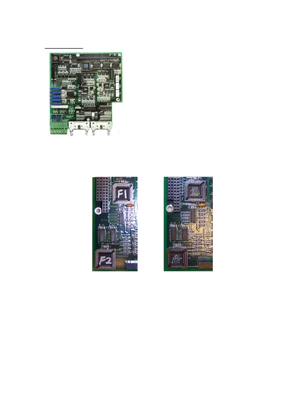
PCIO 1/2 DETERMINATION
Up to two PCIO boards may be a part of the MC³ controller. Note the socketed chips on this
image. If a “second” PCIO Board is added to the card stack, the chip labeled in blue “F1” should
be labeled “2
nd
”. If the second PCIO board is not marked in this manner, it is most likely a first
board and will not work with another first board.
MC3 Hardware Manual 20

 Loading...