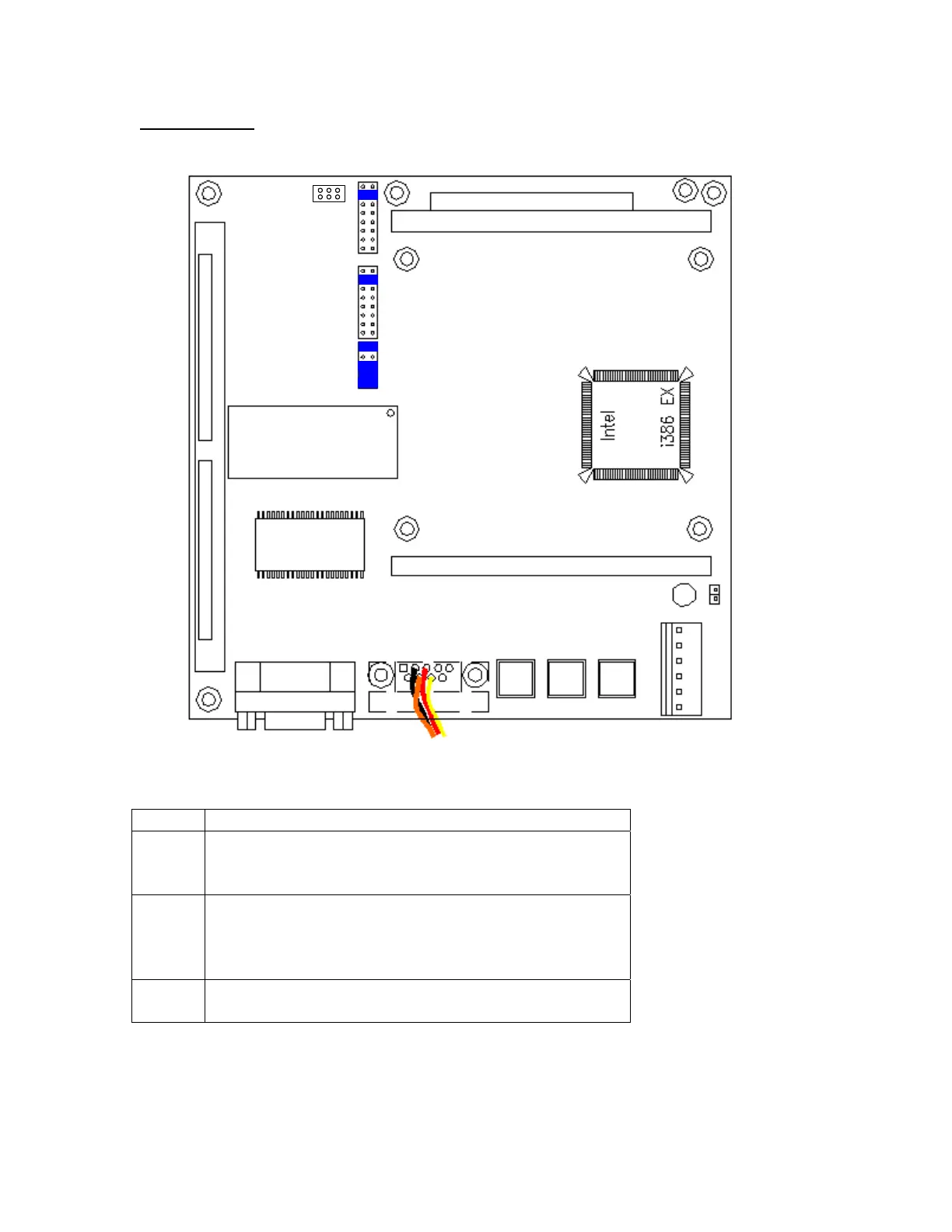
Board Features
COM 1
RS-232
COM 2
RS-485
TO LTI BOARD
RESET
U53A
U14
DALLAS
SRAM
CR1
JP1
FLASHLDR
JUMPER
J1
J2
JP4
JP5
JP6
JP3
PROGRAMMING SIM SOCKET
PF GREEN
+5V RED
+12V YELLOW
-12V BLUE
COM BLACK
COM BLACK
Jumper Settings
Jumper Description
JP1 FLASH PROGRAMMING
Strap to program
Un-strap for Normal operation
JP4 Memory Size
Strap 1 & 2 for 1 to 2 Meg Simm
Strap 3 & 4 for 4 to 8Meg Simm
Strap 5 & 6 for 16+ Meg Simm (may not recognize larger)
JP6 NMI INPUT
Older power supplies connect power fail to pins 3 & 4
Printer Operation (Old CPU Only)
MC³ CPU board must be specifically configured for Printer operation. Call Merrick for details to
verify your CPU board configuration.
MC3 Hardware Manual 16

 Loading...