Pin Description
9 TDI
10 NMI (/Debug Break)
11 TMS
12 CPU Reset
13 TRST# (Normal operation 13/14 are jumpered)
14 PWRGD (Normal operation 13/14 are jumpered)
15 No Connection
16 Flash Lockout (see SW1)
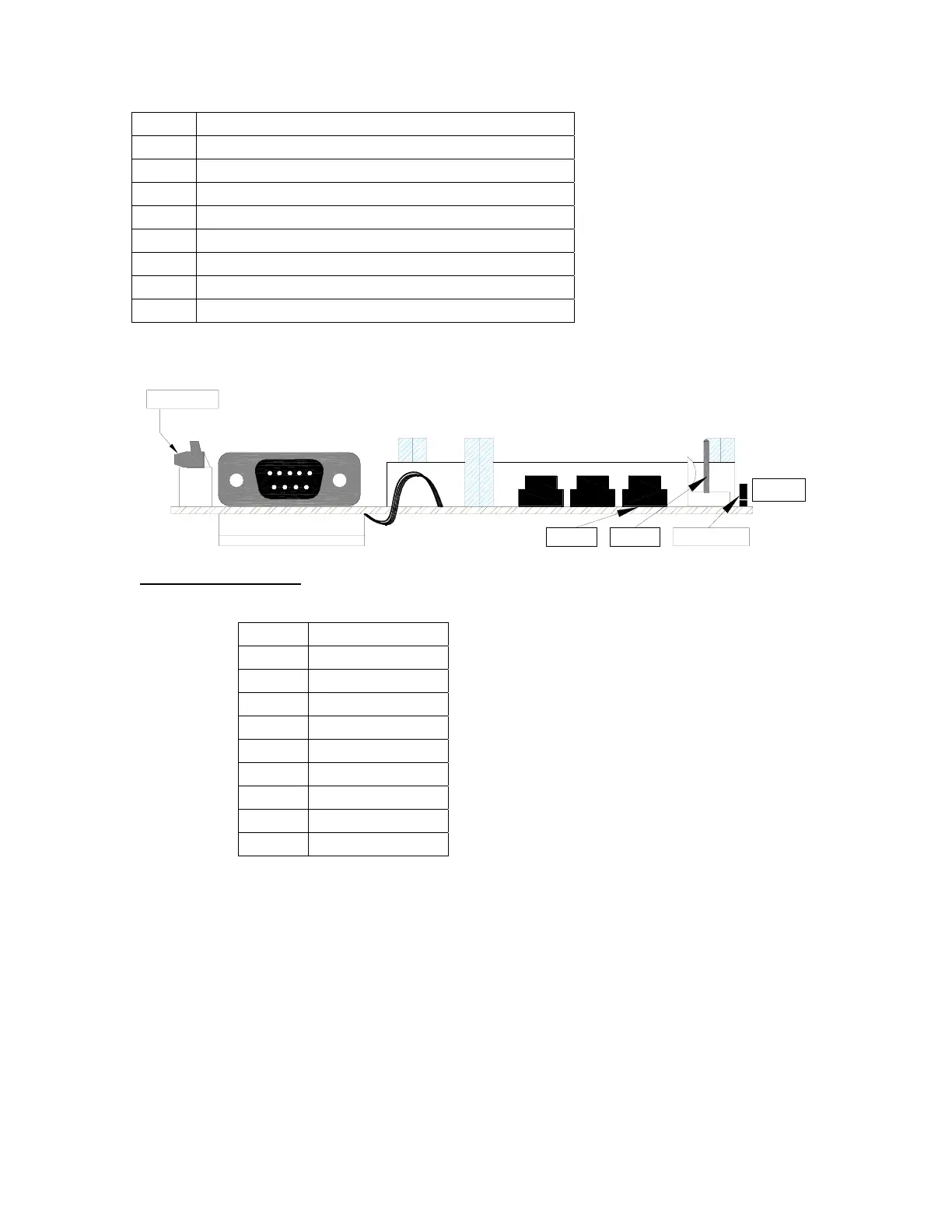
OLD CPU BOARD (REV 10 OR OLDER)
DB9-S (FEMALE)
COMM 2
SIMM SOCKET
(PROGRAMMING)
CABLE
DC POWER
CPU
BUTTON
RESET
PROGRAMMING
JUMPER
Communication ports
Comm 2 (RS-232)
Pin # Description
1 N/C
2 TX Data
3 RX Data
4 N/C
5 Ground
6 N/C
7 Clear to send
8 N/C
9 N/C
The RS-232 serial port is not isolated. There is no RS485 port for Com 2.
The Com 1 serial interface has a 4 wire RS485 port located on the LTI Board (page 23). This port
is isolated from the rest of the MC³ circuits. There is no RS-232 port for Com 1.
MC3 Hardware Manual 15

 Loading...