Option Switch Settings
SW1 Flash Programming Lockout
OFF – Program when SIMM installed
ON – Normal Operation
SW2 Power Fail Detection Level
ON – High Level Detection (Old Style)
Modified Power Supplies
OFF - Low Level Detection
Unmodified Power Supplies
SW3 Test Pin 1 (Led 5/E)
SW4 Test Pin 2 (Led 6/F)
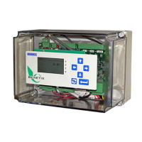
LED Display
LED # Description
1/A Com 2 Receive
2/B Com 2 Transmit
3/C Com 1 Receive
4/D Com 1 Transmit
5/E Test Pin 1
6/F Test Pin 2
7/G Test Pin 3
8/H Test Pin 4
9/I Power Fail
10/J Power ON
8/H, Test pin 4 has a status blink pattern with most firmware applications.
• Two blinks start the sequence (normal)
• A third blink indicate an application fault condition
• A fourth blink indicates a problem with the LCD display.
9/I The Power Fail indicator Blinks once momentarily when the MC³ is powered off.
If it is on
during normal operation, this is an indication that the DC power fail cable between the Power
Supply and the CPU board is not connected, or that SW2 is in incorrect position.
JTAG/Service Port (J8)
Pin Description
1 +5VDC
2 Test Pin 1/LED 5/E
3 GND
4 Test Pin 2/LED 6/F
5 TCK
6 Test Pin 3/LED 7/G
7 TDO
8 Test Pin 4/LED 8/H
MC3 Hardware Manual 14

 Loading...