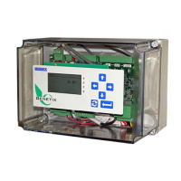
CONNECTIONS
The backplane connections on the PCIO Board, provide the customer with logical on/off signals
to the MC³ Controller. The first backplane board plugs into Backplane 1 on the right. They also
provide digital outputs for controls and status indicators.
+
+--+-
OUT 1
OUT 2 IN 1
ISOLATED ANALOG
BACKPLANE 2
BACKPLANE 1
1 23456
1
16
15
2
1
16
15
2
O
U
T
1
O
U
T
2
O
U
T
3
O
U
T
4
I
N
1
I
N
2
G
N
D
G
N
D
O
U
T
8
O
U
T
7
O
U
T
6
O
U
T
5
I
N
4
I
N
3
+
5
V
+
5
V
135
7
9
11
13 15
246
8
10
12
14 16
DIGITAL I/O PINOUT
PCIO BOARD
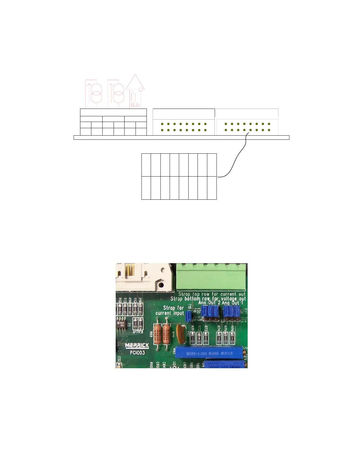
ANALOG I/O CURRENT/VOLTAGE STRAPPING
On the PCIO board are jumpers, to change the analog signals from current to voltage. The
default is current out (straps in top row) and current in (strap in place at T15). When switching an
analog output between current and voltage all three straps must be moved.
This is set for Current input and output
ANALOG INPUT
There is one isolated analog input per PCIO board. If the T15 is jumper installed (current input)
the typical input impedance is 50Ω, and the range is 0..20 mA. If jumper is removed (voltage
input) they typical impedance is 200kΩ, and the range is adjustable 0..1V to 0..10V.
MC3 Hardware Manual 21

 Loading...