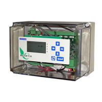
LTI BOARD
The LTI Board contains the circuitry required to process
up to two (single or dual channel) speed encoders,
outputs for an AC and DC Electromechanical Totalizer
(EMT), an RS-485 Serial Port (legacy connector for
older CPU boards) and an interface to the Display
assembly. Supply voltages of +5V and +12V are
located on the terminal block for the speed encoders.
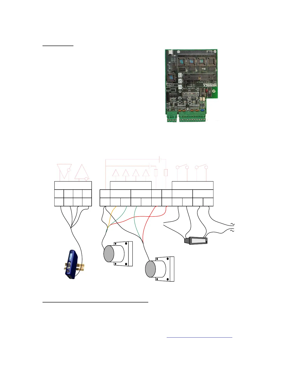
CONNECTIONS
There are 3 types of connections available on the LTI Board: Communication, Encoder and
Totalizer connections. There is +5VDC, +12VDC and Ground available for the encoders. These
signals are detailed on the next page.
EMT (DC & AC)
GND 1A 1B 2A 2B +12V +5V DC EMT AC EMT
Rx-
234567891011
+-
LINE
NEUTRAL
Speed Encoder
Speed Encoder
2 Channel
1 Channel
RS-485
Rx+
Tx-Tx+
11234
TOTALIZERSTACHOS
(5-24VDC)
+24V
COM (110VAC)
HMS AB7000
Serial Communications (for Older CPU Boards)
Serial Channel COMM #1 is a four wire RS-485 port. The baud rate, parity, stop bit settings and
protocols of the ports are setup in the software. For further information on configuring the Serial
Communications Board and its interface to different types of serial equipment, see
Communications found in the Software Manual. For users of the updated CPU board, this
communication port has been moved to the CPU, this port is no longer used. For more
information regarding communications, refer to the website
http://www.merrick-inc.com/mct.
MC3 Hardware Manual 23

 Loading...