ENGLISH
25
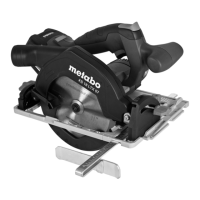
Adjusting the saw:
1. Loosen the ratchet lock lever (71)
for sawhead tilt at the rear of the
saw.
2. Tilt the track arm holder slowly into
the desired position:
Pull the notch lever (72) in the di-
rection of the operator side =
stepless track arm holder adjust-
ment.
Push the notch lever (72) in the
direction of the rear side = locking
the track arm holder in preset
stop positions.
3 Note:
The track arm holder can be engaged
w
ith positive stops at 0°, 22.5°, 33.9°
and 45° angles.
3. Tighten the sawhead tilt lock lever.
A Caution!
In order to prevent the ang
le of inclinati-
on from changing during cutting, tighten
the lock lever of the track arm holder (al-
so when engaged with a positive stop!) .
4. Cut the workpiece as described un-
der 'Mitre cuts'.
7.4 Compound mitre cuts
3 Note:
The compound mitre cut is a combinati-
on of mitre and bevel cuts. This means
the
workpiece is cut at an angle other
than 90° to the rear guide edge and to
its upper surface.
Maximum cut dimensions: see section
'Cut dimens
ions for various cuts'.
ADanger when safety devices
are detached!
Depending on the mitre and bevel ang-
les the fence attachments (halves) may
have to be removed.
Install the fence halves again imme-
diately after cutting!
Without the fence attachments the
h
eight of the fence is insufficient for safe
sawing. Tall workpieces could tip over
backwards!
ADanger!
When cutting compound mitres the saw
blade is
much more exposed than it nor-
mally is – increased risk of injury.
Always maintain a sufficient di-
stance to the saw blade.
Starting position:
– Transport locking pin pulled out.
– Sawhead fully raised.
– Movable fence halves pushed apart
and locked
in place or removed.
– Rotary table locked in desired positi-
on.
– Track arm holder tilted to desired
angle to
the workpiece's surface and
locked in place.
Cutting the workpiece:
Cut the workpiece as described un-
der 'Mitre cuts'.
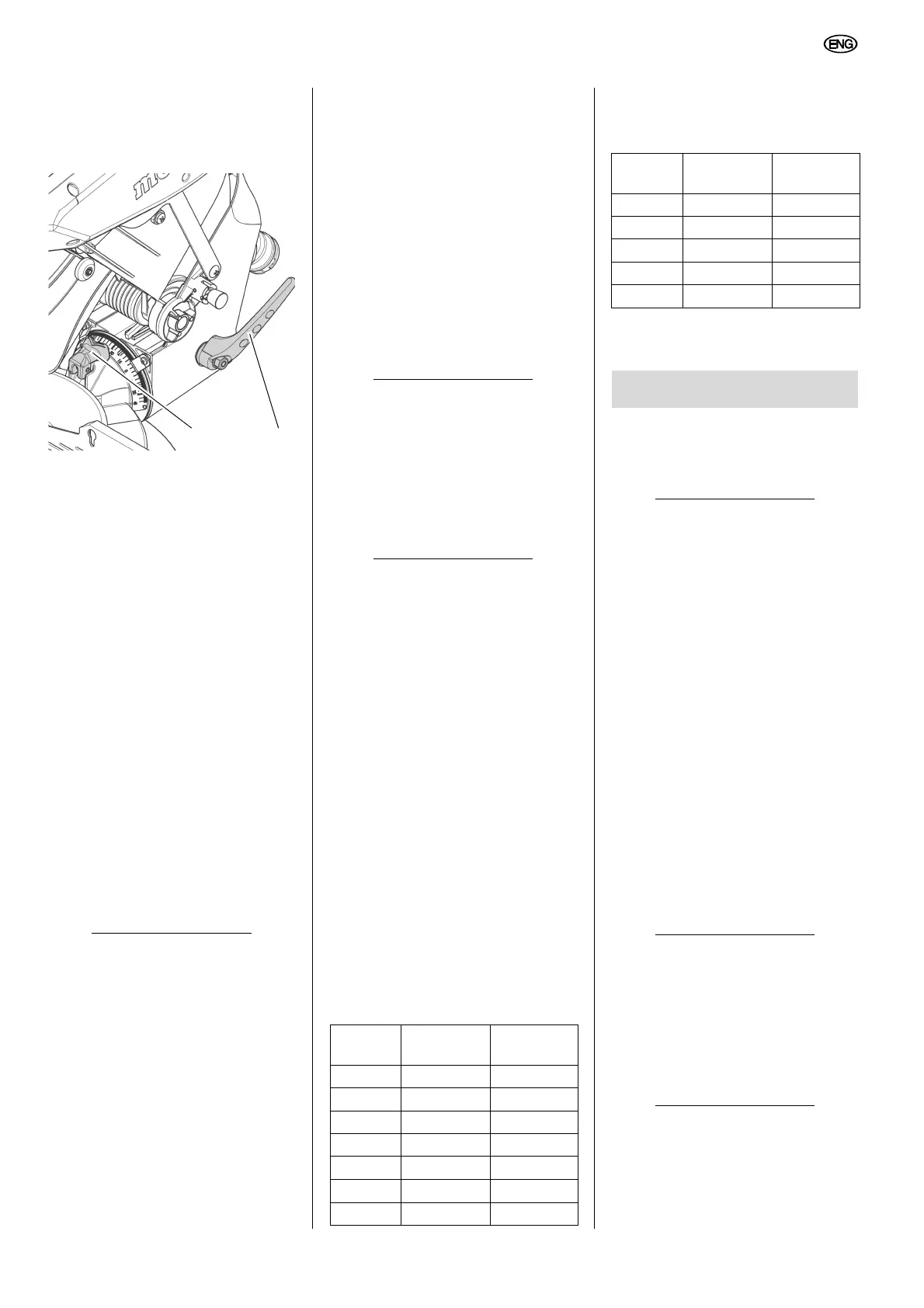
7.5 Cut dimensions for
various cuts
Cutting widths
Maximum workpiece dimensions (in
mm
):
Cutting depths
Maximum workpiece dimensions
(in mm):
* with additional stop
ADanger!
Unplug before servicing.
– Repair and maintenance work other
than described in this section should
only be carried out by qualified spe
-
cialists.
– Damaged parts, particularly safety
d
evices, must only be replaced with
genuine parts. Parts which have not
been tested and released by the ma-
nufacturer can lead to unforeseen
da
mage.
– Check that all safety devices are
oper
ational again after each service.
8.1 Saw Blade Change
ABurn hazard!
Directly after cutting the saw blade can
be ve
ry hot – burn hazard! Let a hot saw
blade cool down. Do not clean a hot
saw blade with combustible liquids.
ACutting hazard - even when
saw blade is at a standstill!
During loosening and tightening of the
arbor bolt, the retractable blade
guard
must encompass the saw blade. Wear
gloves when changing blades.
1. Stop the sawhead in the upper posi-
tion.
2. To keep the saw blade from turning
press the lock knob
(73)
while at the
Mitre KS 254 Plus KS 305
Plus
0° 145 200
15° 140 190
22,5° 130 185
31.6° 120 170
45° 100 140
47° 97 135
58° 75 105
Tilt angle KS 254 Plus KS 305
Plus
0° 90 100*
22,5° 70 75
33.9° 55 60
45° 40 45
47° 33 35
8. Care and maintenance
 Loading...