24
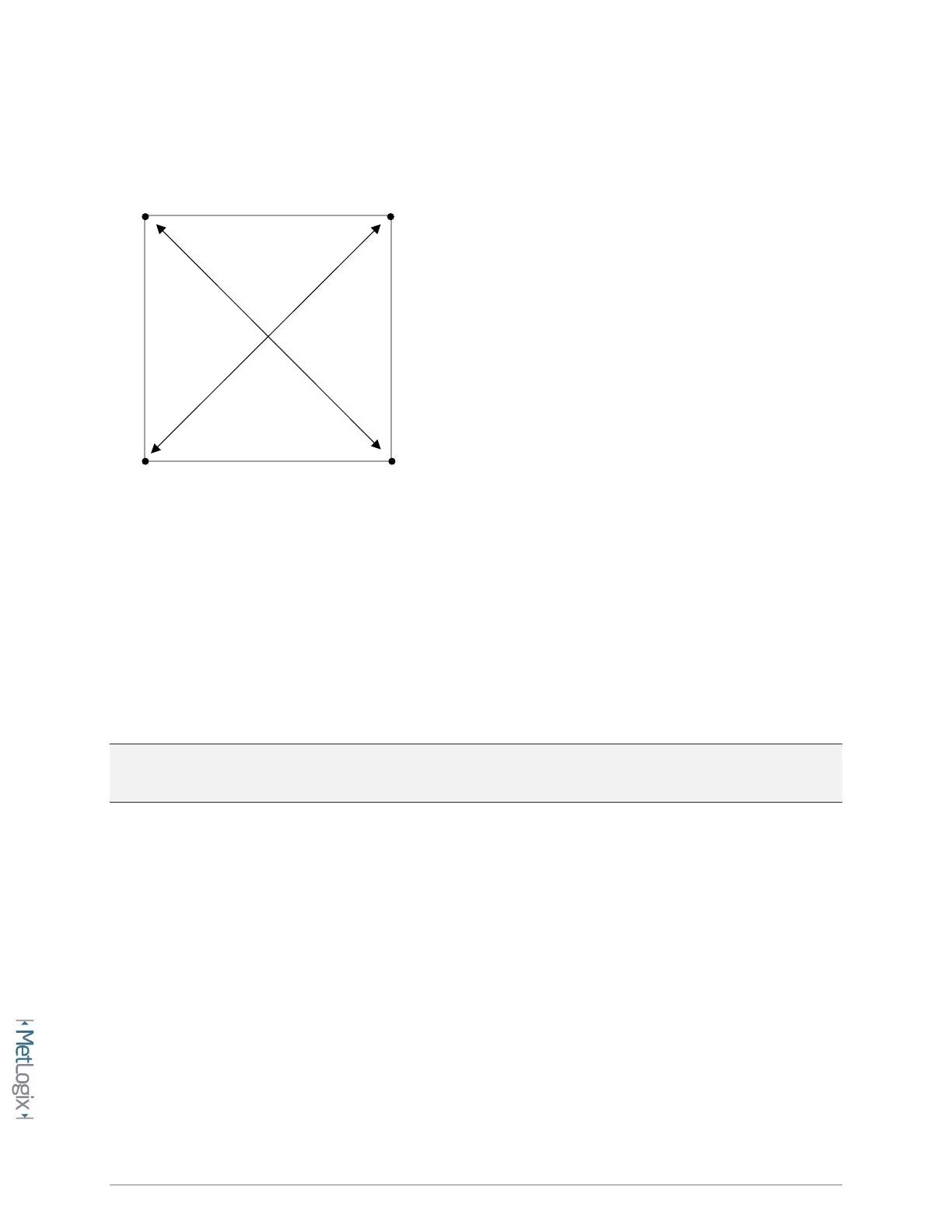
• Construct a distance between each diagonal point pair as seen below.
• Take note of the Length(L) coefficient result for each constructed distance.
• Access the Squareness error correction setup screen.
Mx Button-->Setup-->Error corrections-->Squareness-->XY Squareness
• Enter the (2) recorded Length(L) results into the Tangent and Radial Length fields. After entering
the Lengths into the fields the “Squareness angle” field should get updated to reflect the current
squareness correction angle.
• Set the Enable flag to Yes to activate the squareness correction.
Note: Squareness correction will provide no improvement to the overall calibration of the system if
Non-linear Error Correction(NLEC) will also be applied in the system.
3.2 Entering Linear Error Correction(LEC)
Linear Error Correction(LEC) in the Mx200 applies a linear correction coefficient to the DRO position
reading for any single axis of travel. This calculated correction should reflect the actual amount of
machine/encoder error in a single axis, across the full range of travel of the machine.
LEC is entered into the Mx200 as 2 distinct values, “Standard” and “Observed”. The standard value is the
nominal or certified length of the increment to be used from your calibration artifact, and the observed
value is the actual measurement that the Mx200 produces from that same increment.