Do you have a question about the METREL MI 3122 and is the answer not in the manual?
| Brand | METREL |
|---|---|
| Model | MI 3122 |
| Category | Multimeter |
| Language | English |
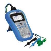
Overview of the instrument's purpose and capabilities for electrical installation testing.
Essential warnings and precautions for safe operation and equipment protection.
Guidance on battery installation, charging, and status indication.
List of international standards and regulations the instrument adheres to.
Detailed overview of the instrument's front panel, buttons, and display elements.
Identification and function of all input and output connectors on the instrument.
Description of the instrument's back panel, including battery compartment and stand.
Explanation of the LCD screen layout, including voltage, battery, message, and result fields.
Listing of standard and optional accessories provided with the instrument.
Instructions for selecting various measurement functions and tests.
Detailed guide to the instrument's settings for language, date, RCD standards, etc.
Comprehensive guide to performing RCD tests: Uc, trip-out time, trip-out current, and autotest.
Procedure for measuring fault loop impedance and calculating prospective fault current.
Procedure for measuring line impedance and calculating prospective short-circuit current.
How to measure voltage, frequency, and determine phase sequence.
Using the PE test terminal to detect dangerous voltages and incorrect wiring.
Understanding the instrument's memory levels and data structure for results.
Instructions for saving, retrieving, and managing stored measurement data.
Procedures for deleting stored measurements, either complete or partial.
Connecting the instrument to a PC for data transfer using EurolinkPRO software.
Proper methods for cleaning the instrument's exterior.
Importance and process for ensuring the instrument's accuracy through calibration.
Contact information and procedures for instrument service and repairs.
Detailed technical data for RCD testing including current, voltage, and time parameters.
Technical specs for loop impedance measurement and fault current calculation.
Technical specs for line impedance measurement and short-circuit current calculation.
Technical data for voltage, frequency, and phase sequence measurements.
Technical specifications for the real-time voltage monitoring feature.
Overall technical details: power, dimensions, operating conditions, and communication speeds.
Tables detailing prospective short-circuit current values for various fuse types.
Tables showing maximum loop impedance for UK-specific fuse types.
Tables for loop impedance values according to AS/NZS 3017 standards.
List of recommended accessories for different measurement functions.
Summary of modifications tailored for specific countries and regions.
Specific details on modifications, including AUS/NZ fuse types and Z factor adjustments.
