MI 3122 Smartec Z Line-Loop / RCD Testing RCD
26
Loop resistance is indicative and calculated from Uc result (without additional proportional
factors) according to:
N
C
L
I
U
R
.
UK version
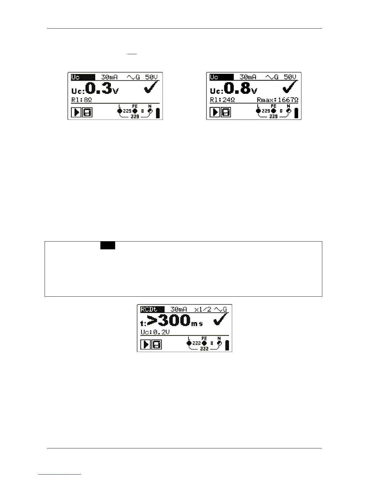
Figure 5.3: Example of contact voltage measurement results
Displayed results:
Uc ....... Contact voltage.
Rl ........ Fault loop resistance.
Rmax .. Maximum earth fault loop resistance value according to BS 7671.
5.1.2 Trip-out time (RCDt)
Trip-out time measurement verifies the sensitivity of the RCD at different residual currents.
Trip-out time measurement procedure
Select the RCD function using the function selector switch.
Set sub-function RCDt.
Set test parameters (if necessary).
Connect test cable to the top of the instrument.
Connect test leads to the item to be tested (see figure 5.2).
Press the TEST key to perform the measurement.
Store the result by pressing the MEM key (optional).
Figure 5.4: Example of trip-out time measurement results
Displayed results:
t .......... Trip-out time,
Uc ....... Contact voltage for rated I
N
.
 Loading...