4 5 FT 70 en
1.4 Technical specifications
Face-to-face length: ASME/ISA S75.04
ASME/ISA S75.03,
IEC/EN 534-3-2 or
ISO 5752 basic ser. 1
Body rating: flanged up to ASME 600, PN 100
flangeless up to ASME 600, PN 100
Max. pressure differential: according to ASME/EN
body/flange rating or
50 bar / 720 psi, whichever is lower
Temperature range: graphite (PTFE lubricated) packing
is recommended for temperatures
exceeding 250 °C / 482 °F
WCC/WCB body-29 to +425 °C
-20 to +797 °F
CF8M body -80 to +425 °C
-112 to +797 °F
1.0619 body -29 to +425 °C
-20 to +797 °F
1.4408 body -80 to +425 °C
-112 to +797 °F
Flow direction: Indicated by the arrow
FTO = flow to open. Flow through
seat ring and past the plug.
Standard flow direction
FTC = flow to close. Flow past
the plug and through the seat ring.
Recommended for erosive
and flashing services.
Tightness: IEC 60534-4 class IV/
FCI 70.2 Cl IV
Mediums: Restrictions determined by
material properties
Dimensions: see Section 11
1.5 Valve approvals
Valve design is based on requirements by EN and ASME
standards.
Fire safety characteristics are defined according to API 607
and BS 6775.
A patent has been issued for the structure of the valve.
ATEX-classification: ATEX II 2G c.
1.6 CE marking
The valve meets the requirements of the European Direc-
tive 2014/68/EU relating to pressure equipment, and has
been marked according to the Directive.
1.7 Recycling and disposal
Most valve parts can be recycled if sorted according to
material. Most parts have material marking. A material list is
supplied with the valve. In addition, separate recycling and
disposal instructions are available from the manufacturer. A
valve can also be returned to the manufacturer for recycling
and disposal against a fee.
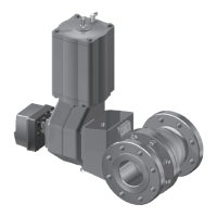
Fig. 4 Maximum allowable pressure drop, A 216 Gr. WCC
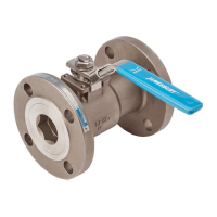
Fig. 5 Maximum allowable pressure drop, A 351 Gr. CF8M
400
200
0
0
20
100
120
100
80
60
40
Pressure (bar)
100 200 300
400300
Temperature (°C)
500
400
200
Temperature (°F)
500 600 700 800 900
1600
1400
1200
1000
800
600
Pressure (psi)
ASME 600
ASME 300
ASME 150
300
Pressure (bar)
60
40
20
0
0
100
80
120
300
100
100 200
200
400 500
Temperature (°C)
ASME 150
400
700600 800
500
900
1000
Pressure (psi)
600
800
200
400
1200
1400
1600
ASME 600
ASME 300
Temperature (°F)
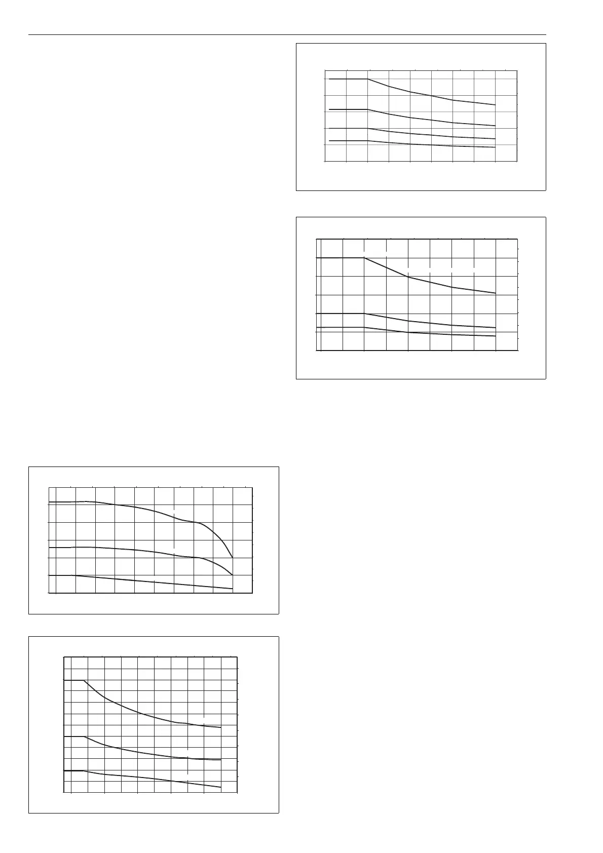
Fig. 6 Maximum allowable pressure drop, 1.0619
Fig. 7 Maximum allowable pressure drop, 1.4408
400
600
800
1000
1200
1400
1600
0.00 100.00 200.00 300.00 400.00 500.00 600.00 700.00 800.00
40.00
60.00
80.00
100.00
Pressure (bar)
Temperature (°F)
0
200
400
0.00
20.00
0 50 100 150 200 250 300 350 400 450
Temperature (°C)
PN25
PN40
PN63
PN100
Pressure (psi)
0
20
40
60
80
100
120
0 100 200 300 400
Pressure (bar)
PN25
PN40
Temperature (°C)
Temperature (°F)
Pressure (psi)
sizes 025, 040, 050 wafer-type only
PN100 (DN25 ... DN50)
100 200 300 400 500 600 700 800
400
200
600
800
1000
1200
1600
1400

 Loading...