3
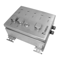
1 LCP9H Local Control Panels for
VG9000H
1.1 General
The Local Control Panels LCP9H-series are designed to be
used together with the VG9000H safety valve controller.
Later on in this manual LCP9H name is used when all ver-
sions (LCP9H, LCP9HW, LCP9HE and LCP9HEW ) are in ques-
tion.
Different versions of LCP9H are following:
LCP9H
Standard version of Local Control Panel LCP9H with
ATEX and IECEx Ex ia, ic approvals
Full functionality
LCP9HE
Explosion proof version of LCP9H with ATEX and Ex d
and tb approvals
Full functionality
LCP9HW
Same approvals than LCP9H
Close(/open) functionality is removed
LCP9HEW
Same approvals than LCP9HE
Close(/open) functionality is removed
This manual only describes the Local Control Panel LCP9H
wiring, configurations and functions. See the VG9000H
manual (7VG92H70en) for detailed information, functional-
ity and wiring connections and options for the VG9000H.
1.2 Technical description
LCP9H and LCP9HE permit the emergency isolation valve to
be closed (or opened) locally (close/open functionality, see
4.1.1 for details). This functionality is removed from
LCP9HW and LCP9HEW. LCP9H permits the valve to be
returned to the normal operating position when the trip ini-
tiators are normal (manual reset functionality, see 4.1.2 for
details). There is also the option for functional testing (PST)
of the emergency isolation valve (test functionality, see
4.1.3 for details).
LCP9H-series devices also have indicators (LEDs) for the
valve position (open/close), ready to reset, testing and
alarm status (see 4.1.4-7 for LED details).
All the buttons are lockable with e.g. padlock (max. shackle
dia. 5 mm).
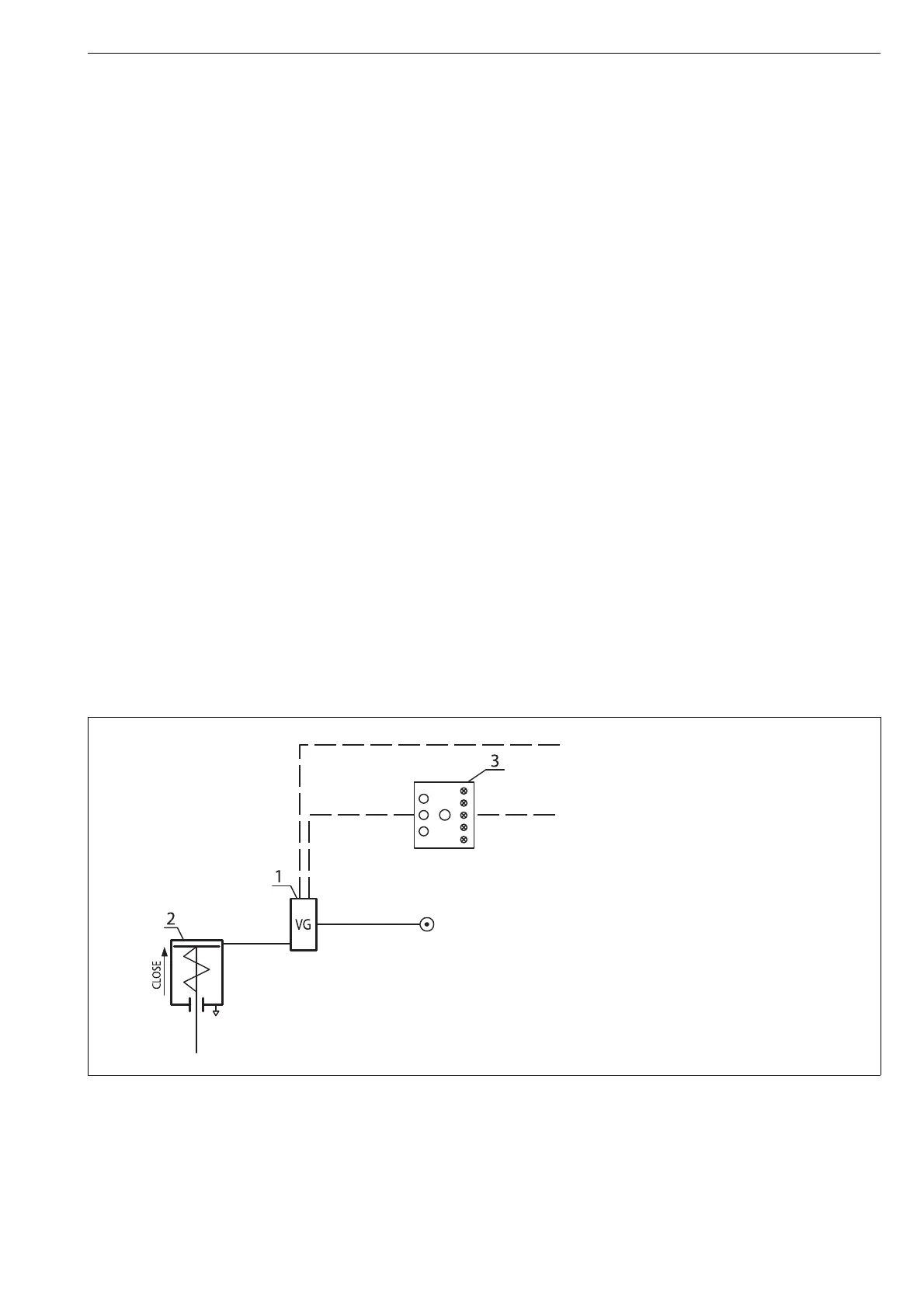
1.3 System architecture
The Local Control Panel LCP9H is connected to the
VG9000H with a dual pair twisted cable. Communication
between the devices is handled by a current loop. The
LCP9H also needs a 24 V DC power supply. Refer to the gen-
eral wiring of the LCP9H in Fig. 1. See detailed wiring infor-
mation in Section 3.2.
If the LCP9H is used in intrinsically safe installations, an iso-
lator will be needed for the 24 V DC power supply, see 1.5
for compatible isolators.
Fig. 1 General wiring of LCP9H / VG9000H
Air supply
1. ValvGuard VG9000H
2. Pneumatic actuator
3. Local Control Panel LCP9H
AO (mA)
from safety system (or from RCI9H)
24 V DC supply
(via isolator if required)
Serial
communication
 Loading...