6
NOTE: The VG9000H version to be used with LCP9H prod-
ucts needs to have type code option L2. In VG9000H the
LCP connection terminals (7-10) are located in the upper
housing.
See the VG9000H manual 7VG9H70EN for detailed electrical
connections in the VG9000H.
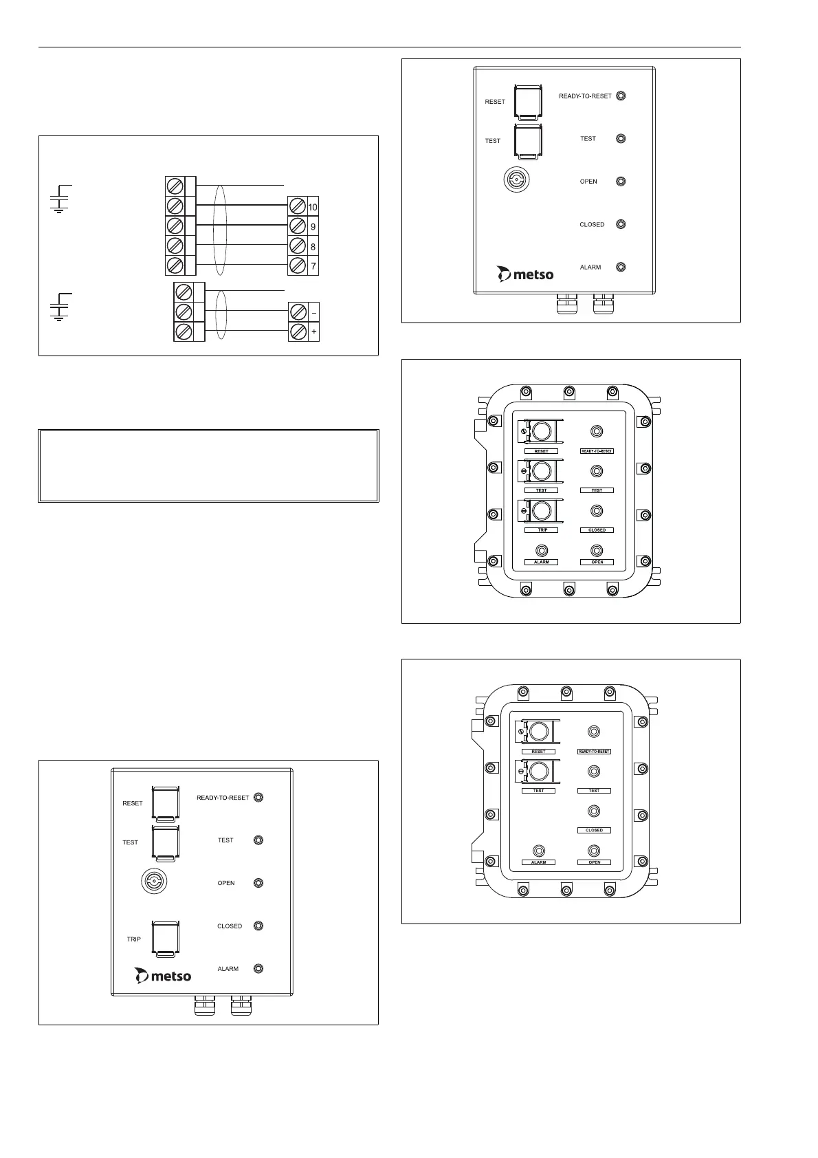
4 LCP9H LAYOUT AND FUNCTIONALITY
The LCP9H front panel layouts with push buttons and LEDs
can be seen in Fig. 5–8.
The push buttons (described in the Section 4.1) are as follows:
Reset
Test
Trip
The LEDs (described in the Section 4.1) are as follows:
Ready-To-Reset (amber)
Test (amber)
Open (green)
Closed (red)
Alarm (white)
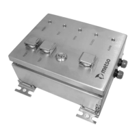
Fig. 4 LCP9H electrical connections
NOTE:
When installing the LCP9H, standard IEC 60079-14/12.2.4
should be considered. The circuits of the apparatus are
assumed to be earthed.
Fig. 5 LCP9H front panel
VG9000HLCP9H
LOOP_CHGND
LOOP_B-
LOOP_B+
LOOP_A-
LOOP_A+
PWR_IN_CHGND
PWR_IN-
PWR_IN+
24 V DC
supply
ground
ground
Fig. 6 LCP9HW front panel
Fig. 7 LCP9HE front panel
Fig. 8 LCP9HEW front panel
 Loading...