CHAPTER 3: CAL USER PANEL
18
LOGIC I/O PORTS
The Logic I/O connectors provide a range of control and
monitoring for CAL, including changing presets, overriding
and muting the input signal, monitoring loudspeaker faults,
and providing voltage output. The Logic I/O connectors are
optically isolated from the CAL loudspeaker circuitry. The
three COM pins are isolated from each other to set the
reference voltage for their associated logic pins. A logic pin
is triggered when it receives a voltage of 3 to 20 V DC
greater than its associated COM voltage.
CAUTION: Do not send voltages greater than
20 V DC to the Logic I/O pins as this may dam-
age the input circuitry.
Presets 1–4
CAL presets recall loudspeaker settings for beam control
and processing (5-band parametric EQ, gain, and delay).
Presets are edited in Compass Control Software. An
unlimited number of presets can be saved and stored on
your computer but only four presets can be stored in the
CAL loudspeaker. When CAL is not connected to a
computer, presets can be selected by sending control
voltages to the A1 and A2 pins.
Table 1 illustrates the logic for selecting presets with control
voltages.
For example, to select preset 2, a voltage of 3 V DC is sent
to the A1 pin while 0 V DC is sent to the A2 and COM pins.
NOTE: The A1 and A2 pins are triggered when
receiving a voltage of 3 to 20 V DC greater than
their associated COM voltage.
CAL Factory Presets
A summary of the beam settings for the CAL factory presets
is shown in Table 2. CAL ships from the factory with these
presets loaded into the loudspeaker. The presets can be
edited and overwritten with Compass Control Software.
NOTE: For more information, refer to the
Compass support videos (available at
meyersound.com/product/compass/#support-
videos).
The Fault Contact pins report when CAL shuts down or is no
longer active. When CAL is powered on and working
normally, the NO (normally-open) pins are open and the NC
(normally-closed) pins are shorted together. When the
loudspeaker is powered off, its internal relays switch so that
the NO (normally-open) pins are shorted and the NC
(normally-closed) pins are opened. The three Fault Contact
pins are provided to accommodate monitoring for either
short circuits or open circuits.
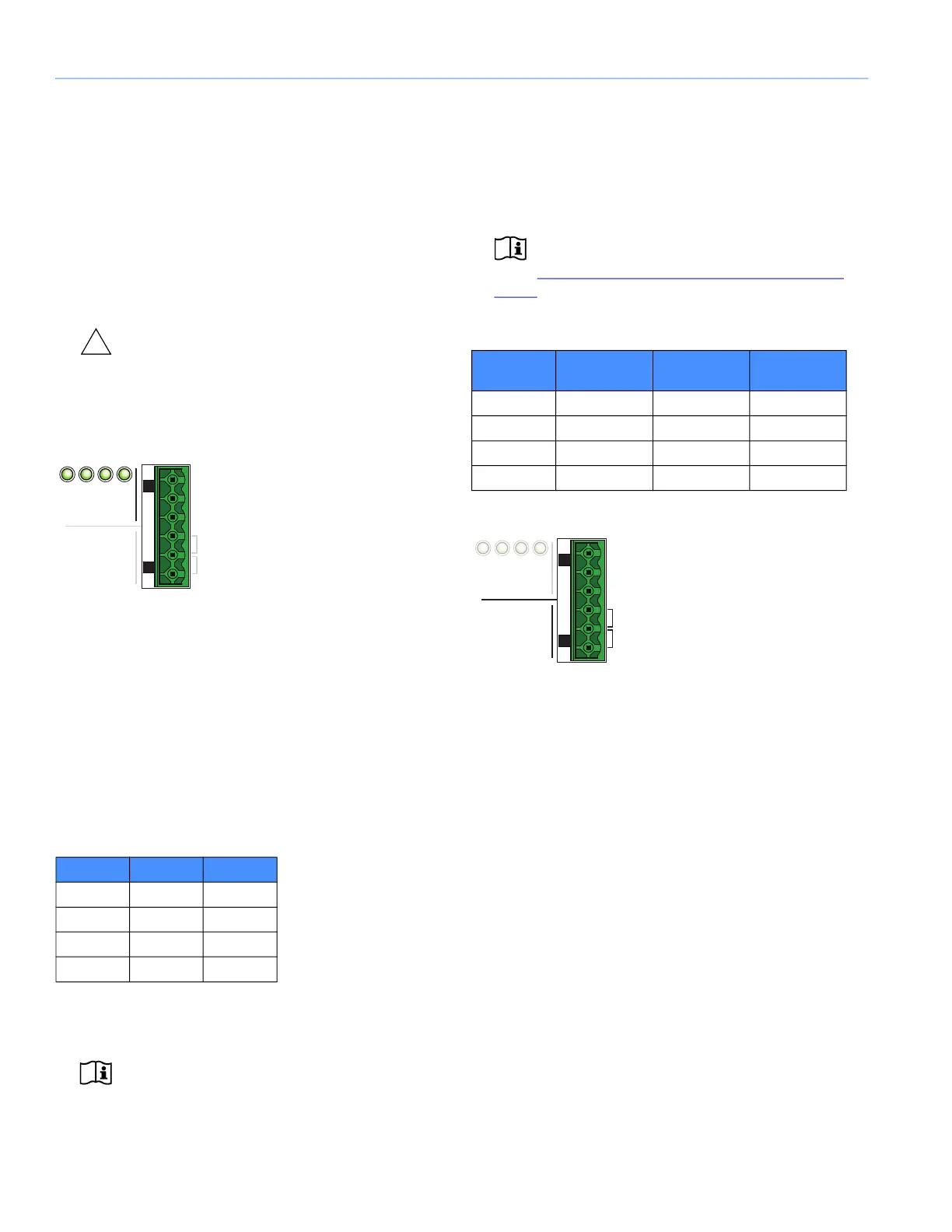
Preset Pins
Table 1: CAL Preset Selection Logic
A1 A2
Preset 1 0 0
Preset 2 1 0
Preset 3 0 1
Preset 4 1 1
NO
1 2 3 4
Preset
com
a1
a2
Fault
Contact
NC
Table 2: CAL Factory Presets
Vertical Beam
Angle
Vertical Beam
Spread
Vertical Beam
Split
Preset 1 0° 5° None
Preset 2 5° 5° None
Preset 3 -17° 25° None
Preset 4 -30° 5° None
Fault Contact Pins
NO
1 2 3 4
Preset
com
a1
a2
Fault
Contact
NC
 Loading...