CAL OPERATING INSTRUCTIONS
25
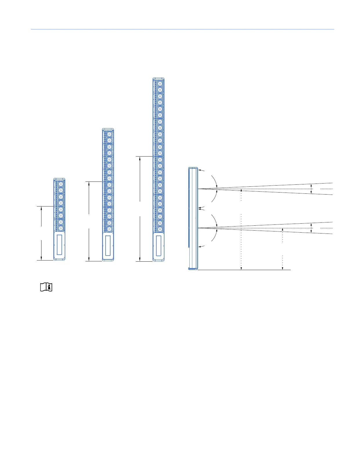
Figure 1 illustrates the vertical acoustical center points for
the three CAL models, from which the beams emanate. The
acoustical center points also represent the axis for beam
angles.
NOTE: For the acoustical center points of
beam split configurations, see “Vertical Beam
Splits.”
VERTICAL BEAM SPLITS
The CAL 64 and CAL 96 models include beam split
coverage modes to aim sound toward two destinations or to
avoid reflective surfaces such as a balcony. The beam splits
can also be configured with beam angles (see “Vertical
Beam Angle” on page 24) and beam spreads (see “Vertical
Beam Spread” on page 24).
CAL 64 Center Split Beams
The CAL 64 model includes a center split beam coverage
with the top beam emanating from the top 32 drivers and
the bottom beam emanating from the bottom 32 drivers.
Figure 2 shows a CAL 64 with center split beams, each with
5
° beam spread. Also illustrated are the beams’ acoustical
center points.
Figure 1: Acoustical Center Points for CAL 32, CAL 64, and CAL 96
35.70
[907 mm]
69.10
[1755 mm]
52.40
[1331 mm]
Figure 2: CAL 64 Center Split Beams with 5° Beam Spread
87.5°
87.5°
5°
87.5°
87.5°
5°
69.10
[1755 mm]
35.69
[907 mm]
 Loading...