CHAPTER 2: HD-1 SETUP
8
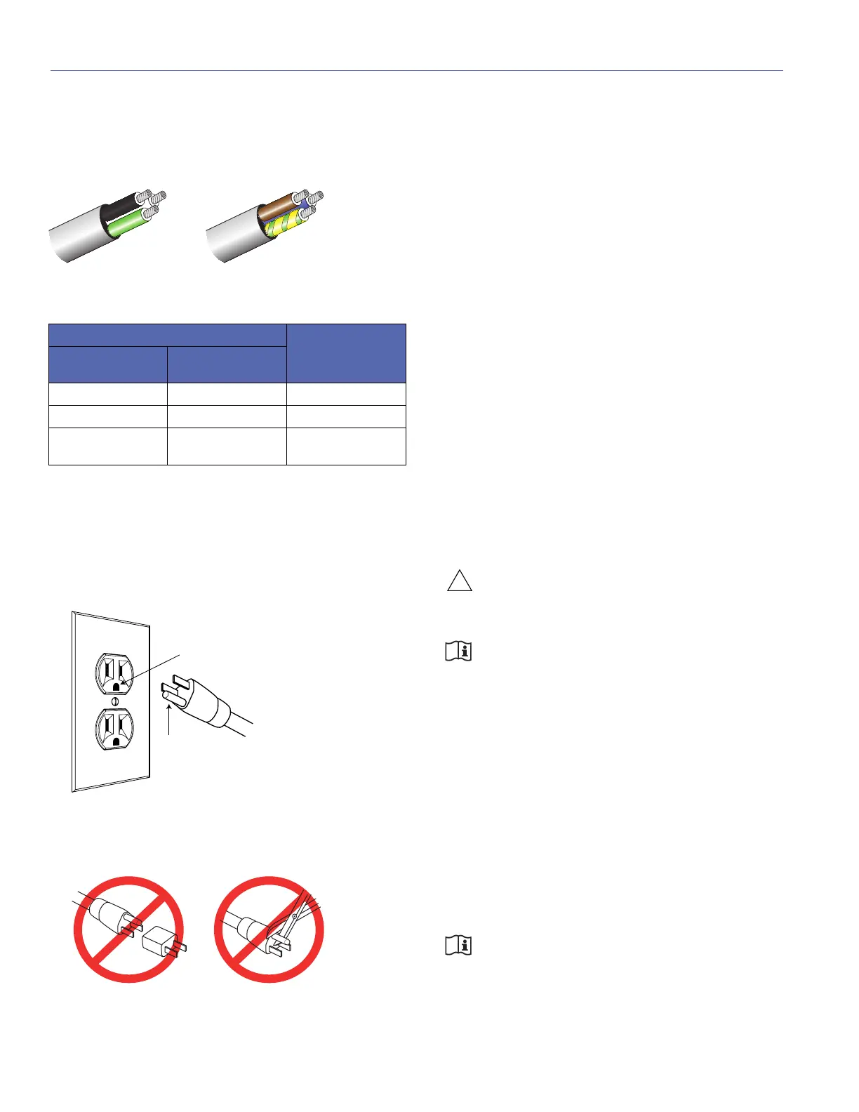
AC Power Cable Wiring
When wiring international or special-purpose AC power
cables, use the following wiring scheme:
Electrical Safety Guidelines
Pay close attention to these important electrical and safety
guidelines.
■ The HD-1 requires a grounded outlet. Always use a
grounded outlet and plug.
■ Do not use a ground-lifting adapter or cut the AC power
cable ground pin.
■ Make sure the AC power cable for the loudspeaker has
the appropriate power plug for the area in which you will
operate the loudspeaker.
■ Do not operate the unit if the power cable is frayed or
broken.
■ The AC power connector must not be engaged or disen-
gaged when under load or live.
■ Keep all liquids away from the HD-1 to avoid hazards
from electrical shock.
INPUT CONNECTOR
The HD-1 receives audio from its XLR 3-pin female Input
connector, which uses the following wiring:
■ Pin 1 — Audio common
■ Pin 2 — Signal (–)
■ Pin 3 — Signal (+)
■ Case — Earth (AC) ground
The Input connector accepts 10 kOhm balanced audio sig-
nals. Make sure to use standard XLR audio cables, with all
three pins connected on both ends, for balanced audio sig-
nals. Unbalanced audio signals require an inline adapter.
CAUTION: Shorting an Input connector pin to
the case may cause a ground loop, resulting in
hum.
NOTE: Meyer Sound offers an optional RCA
male to XLR 3-pin male audio cable for con-
necting to source devices with RCA outputs.
INPUT LEVEL
The Input Level switch determines the input sensitivity for
source signals connected to the HD-1’s Input connector.
The Input Level can be set to:
■ +4 dBu (1.23 V rms = 114 dB SPL rms): Select this
option for balanced audio signals, usually from profes-
sional audio equipment.
■ –10 dBV (0.32 V rms = 114 dB SPL rms): Select this
option for unbalanced audio signals, usually from con-
sumer or semi-professional audio equipment.
NOTE: Setting the Input Level to –10 dBV
when receiving a +4 dBu source signal will
result in increased noise.
AC Wiring Scheme
Wire Color Attach to the
Following
Term inal
U.S. / Canada
60 Hz
European
50 Hz
Black Brown Hot or live (L)
White Blue Neutral (N)
Green Green and Yellow Protective earth /
ground (E or PE)
U.S./Canada, 60 Hz
Black (L)
Europe, 50 Hz
Green (E)
White (N)
Brown (L)
Blue (N)
Green/
yellow (E)
Earth ground
Chassis ground
 Loading...