20
CHAPTER 4
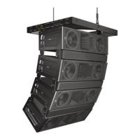
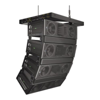
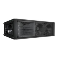
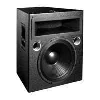
MILO and the 650-P Subwoofer
In applications where M3D-Sub features like directional low-
frequency control and additional peak SPL are not needed,
a MILO array can be deployed in combination with Meyer
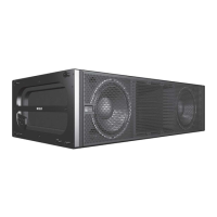
Sound 650-P subwoofers. The 650-P subwoofer extends
the MILO system frequency response down to 30 Hz; MILO
and the 650-P can accommodate three basic connection
options.
Daisy-Chained
When MILO loudspeakers and 650-P subwoofers are daisy-
chained using the loop feature on the user panel, the result
is a fairly at frequency response (and a rise in the 80 to
150 Hz range where the loudspeakers’ response overlaps)
at a ratio of two MILO loudspeakers to each 650-P. While
there is no polarity switch on a MILO loudspeaker, the 650-
P does indeed have a polarity switch, and you will need
to ensure that the 650-P is set to pin 3 + (reversed with
respect to a MILO loudspeaker’s pin 2 +) when co-planar
and in close-proximity to your MILO array.
CAUTION: Make sure that the source device
can drive the total load of the paralleled
array. (See Audio Input section, page 9)
NOTE: When both a MILO loudspeaker
and a 650-P are used in their full-range
conguration (e.g. looped audio or the same audio
feed), their polarities should be kept reversed (set
the switch on the rear of the 650-P to Pin 3 +) if
they are co-planar or near each other. If they are
separated by a greater distance – or delay must be
used between them – a measurement system such
as SIM should be used to determine the correct
delay and polarity.
Adding an LD-1A/LD-2 Line Driver
Driving MILO loudspeakers and 650-P subwoofers with the
same signal from different outputs using a line driver allows
adjustments to the gain and polarity of each sub-system,
and could be used effectively to compensate for the ratio
of loudspeakers or acoustical conditions. If the gains are
adjusted to the same level, the combined response is
identical to a daisy-chain conguration.
When driving MILO loudspeakers from the Mid-Hi output
of the LD-1A or LD-2 line driver, with 650-P subwoofers in
their full-range conguration, their polarities should be kept
reversed if they are co-planar or near each other. The best
way to achieve this is to set the switch on the rear of the
650-P to Pin 2 + and control the 650-P polarity using the
LD-1a or LD-2 by inverting sub-out polarity. If your MILO
loudspeakers and 650-P subwoofers are separated by a
greater distance – or delay must be used between them
– a measurement system such as SIM should be used to
determine the correct delay and polarity.
Using the LD-1A or LD-2’s Lo-Cut lter can keep the
MILO loudspeaker and 650-P subwoofer (when co-
planar) in phase with a minimal area of overlap; the MILO
loudspeakers in the array receive their signal following a
high-pass lter, while the 650-P subwoofers apply their
normal internal crossover frequencies to a full range signal.
Frequency response using this conguration remains at,
though there is a slight rise from 80–100 Hz due to the
natural response shape of the 650-P.
TIP: How at the response will be is, in any
case, dependent on proximity to boundary
surfaces.
To drive MILO loudspeakers from the Mid-Hi output of the
LD-1A line driver (Figure 4.5) or the LD-2 line driver (Figure
5.6), the Lo-Cut lter is engaged with no polarity reversal on
the 650-P Sub’s output set to pin 2 +. Simply change the
650-P subwoofer’s user panel to pin 2 + and the line driver’s
sub output to “normal”.
While the change of polarity with respect to a daisy-chained
conguration is needed due to the phase shift caused by
the high-pass lter at overlapping frequencies, placing the
subwoofers more than 4 feet apart may require reversing
the polarities once again to compensate for the delay
propagation.
NOTE: When driving MILO loudspeakers
from the Mid-Hi output of the LD-1A or LD-2
line driver – with the Lo-Cut lter engaged - and
650-P subwoofers in their full-range conguration,
their polarities should be kept the same if they are
co-planar or near each other.
If your MILO loudspeakers and 650-P subwoofers
are separated by a greater distance – or delay must
be used between them – a measurement system
such as SIM should be used to determine the
correct delay and polarity.
Adding an LD-3 Line Driver
In addition to its unique atmospheric correction capabilities,
Meyer Sound’s LD-3 air attenuation compensating line
driver (Figure 4.7) can be used effectively to manage low-
frequency build-up and integrate subwoofers in a design
with MILO arrays.